Delayed Generation
 When you tell an object that it is to be a
certain stitch type, the stitches will automatically generate. Also, when you
adjust or edit the object, the stitches will generate for you. But what if you
want to do a complex series of edits on the object? It might be desirable to
turn the automatic generation off for a while. You can do this with the ‘Delayed
Generation’ button. As long as the button is pressed, and you are in ‘Create’
mode, your stitches will not generate.
When you tell an object that it is to be a
certain stitch type, the stitches will automatically generate. Also, when you
adjust or edit the object, the stitches will generate for you. But what if you
want to do a complex series of edits on the object? It might be desirable to
turn the automatic generation off for a while. You can do this with the ‘Delayed
Generation’ button. As long as the button is pressed, and you are in ‘Create’
mode, your stitches will not generate.
Generate Now
 When you
want to generate stitches on an object or set of selected objects, click the
‘Generate now’ button. If nothing is selected, the program will look for any
objects needing to be generated and will generate them accordingly. This button
is useful when Delayed Generation is turned on – you control what gets generated
and when.
When you
want to generate stitches on an object or set of selected objects, click the
‘Generate now’ button. If nothing is selected, the program will look for any
objects needing to be generated and will generate them accordingly. This button
is useful when Delayed Generation is turned on – you control what gets generated
and when.
Default Drawing of Line/Curve
 The usual
mode of drawing with points is to draw with curved points and use the Ctrl key
to draw a line. This may be undesirable for some art. You can use this button to
switch the way that operates – pressing it will cause drawing to default to a
line, and the Ctrl key will cause points to be a curve. Note that using the
Shift key to make a line constrained to 15-degree angles will work either way –
you can constrain the line angle as long as you are not making a curve.
The usual
mode of drawing with points is to draw with curved points and use the Ctrl key
to draw a line. This may be undesirable for some art. You can use this button to
switch the way that operates – pressing it will cause drawing to default to a
line, and the Ctrl key will cause points to be a curve. Note that using the
Shift key to make a line constrained to 15-degree angles will work either way –
you can constrain the line angle as long as you are not making a curve.
Auto-scroll Toggle
 When
drawing, the edges of the main view have an area that act as an auto-scroll area
– if you move your mouse in that area while drawing your page will scroll
automatically which gives you more room to continue drawing. Sometimes this is
undesirable, and the action can be toggled on and off using this button. Note
you can also use the arrow keys while drawing to scroll 1cm per key click. And
holding the spacebar will let you pan the screen by dragging it with the
mouse.
When
drawing, the edges of the main view have an area that act as an auto-scroll area
– if you move your mouse in that area while drawing your page will scroll
automatically which gives you more room to continue drawing. Sometimes this is
undesirable, and the action can be toggled on and off using this button. Note
you can also use the arrow keys while drawing to scroll 1cm per key click. And
holding the spacebar will let you pan the screen by dragging it with the
mouse.
Selection by Style or Type
When an object is selected, you can select all other objects
using the same style or stitch type by adding the Control key to a right-click.
Ctrl-Rt-Click > Select by…
 Areas
filled with stitches such as Satin Columns and Fills can be given additional
texture using Carving Lines. Carving lines are additional shapes that can be
added to objects in a very similar manner to adding holes. Use the ‘Add Carving
Line’ button on the Tool Pane to begin a carving line, and select the input
method (usually Point Input) to begin drawing. Draw a path over the object.
Areas
filled with stitches such as Satin Columns and Fills can be given additional
texture using Carving Lines. Carving lines are additional shapes that can be
added to objects in a very similar manner to adding holes. Use the ‘Add Carving
Line’ button on the Tool Pane to begin a carving line, and select the input
method (usually Point Input) to begin drawing. Draw a path over the object.
The carving line generates needle penetrations where the
normally-generated stitches intersect the carving line.
The only real caveat to carving lines is that in high-density
areas, your fabric may lash up as the needle is penetrating closely together.
For this and other reasons, some designers create two areas of fill, overlaid on
one another, each at half density. This adds texture, can reduce fabric pull,
and carved lines will add minimal impact.


Using Styles
Styles allow for repeated use of properties on a given type of
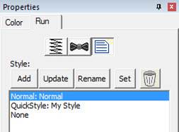
object. There is a style button on the top, right of each object property page.
When an object has been assigned a style, that style will be highlighted in the
style list, shown on the Style properties for the object. If an object was
assigned a QuickStyle, but has been modified, it will be given an asterisk at
the end of the style name.
Once you change the property of an object you just made, the
program takes the properties of that object and uses them for the next object
you make of the same type. This is the “Current Style.” For example, if you
create a run and set it to a Bean stitch, the next run you create will start out
as a Bean also. Although it may not be a named style, the current properties are
important, as they are used when creating an object.
Updating the ‘Current’ Style
The ‘Set’ button will use all of the properties as shown to
set the ‘Current’ style for new object creation; when you create a new object of
that same type (run, column, etc.) it will be created with the same settings as
the first object now selected.
Alternately, if you have an object whose style is “None” and
you click ‘Update’ it will likewise set the ‘Current’ digitizer settings to
match that object.
Normal Style
When you begin creating objects having just run the program,
the default styles are being used, called “Normal.” These have been tested to be
reasonable for all-around conditions, but naturally properties exist for a
myriad of reasons.
To remove the QuickStyle from an object, click “None.” This
will have no effect on the properties of the object; it just removes the style
setting.
When you have an object that has its properties set a certain
way, you can save those properties as a QuickStyle. Using QuickStyles allows you
to remember a set of property settings that sewed perfectly for a project, or
simply to match prior objects you’ve created.
Adding a QuickStyle
When you create a style based on a selected object, you can
name it. This is called a QuickStyle, and the style itself resides with the
design page being used, and on your computer for future use. To do this, click
the ‘Add’ button.
If you load a document with a style that is not on your
system, it will be referred to as a “Page Style”. If you would like to add this
style to your collection for use later, you can click the ‘Add’ button.
Renaming a QuickStyle
If you wish, you can rename the style with the ‘Rename’
button. Any object that uses this style will show the new name in use when the
style page is shown.
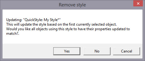
Updating a QuickStyle
When you have modified a QuickStyle-stylized object, and you
want to update the QuickStyle to match the current object properties, use the
‘Update’ button. This means that other objects with the same style set will not
match. Since the main reason for styles is to have all the objects working the
same, there is an option presented to update all the other objects that use the
same QuickStyle to have their properties match the current one.
Removing a QuickStyle
Using the ‘Remove’ button, with the trash can icon on it, you
will remove the QuickStyle from the page, and from your system. Realize in doing
so that other objects on the page, or indeed other files you have created, may
have used that QuickStyle.
As QuickStyles are stored with the page as well, the style
will become a “Page Style” for other documents when you load them, if they had
that QuickStyle applied.
When you remove a QuickStyle, it erases it completely without
affecting the properties themselves. Objects that have had their QuickStyle
removed will not lose their property settings, but will naturally have a style
setting of “None.”
Stylesheets are design collections that have objects that have
properties set to perform digitizing a certain way.
For example, suppose you want to collect a set of object types
that you use to create freestanding lace. You can make a design with those
objects in it. Their shape does not matter, but their properties are what are
important. The objects will have the properties needed to make your lace. You
can then use that Stylesheet at any time to set all the object properties on the
sheet.
Stylesheets allow you to add styles to your Styles lists
quickly and easily. They can also be exported in a .BX installer for use on
multiple computers, or even shared with others.
Stylesheets can be loaded into the ‘current’ digitizer
settings, usually at the onset of creating a new design, but not always – they
can be set as the current properties at any time.
Creating a Stylesheet
Start with a new design page. Now begin by digitizing one
object, and set the properties of that object to your style. You can use a
QuickStyle that you have on hand already to set the properties. You can add as
many objects to the design as you like. Once you have the design how you want
it, use the menu ‘Create->Publish->Stylesheet’:
 ’
’
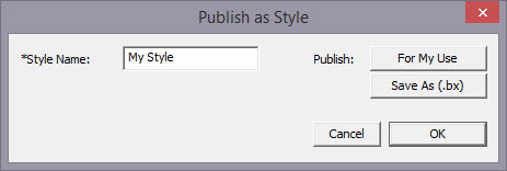
You now have two options for Publishing: Publishing to your
collection of Stylesheets, or publishing as a .BX installer. The .BX option will
also publish to your stylesheet list, but it additionally saves a .BX file to a
location of your choosing.
Here is an example:
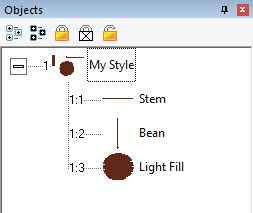
In this screenshot, you can see we have two Run objects,
labeled ‘Stem’ and ‘Bean’. We also have a Fill object, labeled, ‘Light
fill’.
IMPORTANT: Save your working (.be)
file so you can adjust this Stylesheet at a later date if you need
to.
When we publish this Stylesheet, we have these available as
QuickStyles:
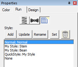
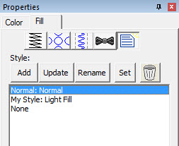
Notice there are now two entries on the Run (left) and one on
the Fill (right).
Setting a Style as Current
The menu ‘Create->Styles…’ calls up the Stylesheet
manager:
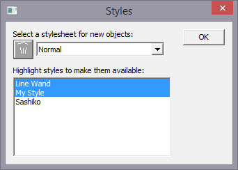
This window is divided into two sections. On the top is a list
of the Stylesheets available to be used to set the ‘current’ properties. The
lower list allows you to highlight any and all Stylesheets you want to have
available for use while creating a design.
Thus, you are not limited to a single Stylesheet, nor are you
restricted to using it only at the start of a design page. You can set the
properties to a style at any time by selecting it in the drop list. And you can
highlight as many stylesheets to be available as you like.
You will notice there are some Stylesheets that exist for you;
Normal (which is the default properties for the program) and ‘Line Wand’ which
is handy to use when generating objects with the ‘Magic Wand Lines’ tool. You’ll
notice that in the image above, there are two Stylesheets selected, “Line Wand’
and ‘My Style’, so here is what we see in the Run properties:
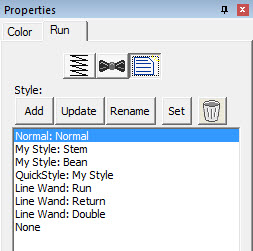
Notice that there are ‘My Style’ and ‘Line Wand’ available.
Also, we had chosen ‘Normal’ as the Stylesheet to use as a current property set,
so the Normal is there as well.
Note that QuickStyles are always available to you; they are
not a particular Stylesheet, but rather a simple set of properties for one
object type.
Removing a Stylesheet
When you select a Stylesheet that you have created, the
trashcan button next to the drop list will be active, allowing you to remove
that Stylesheet from your system completely. (Remember, we told you to save the
.BE file in case you want it later!)
Path Operations
Path operations are advanced graphical tools that help you
quickly get a result shape based on currently selected ones.
 Sometimes
you would like to be able to take a pair of scissors to a shape – make a wavy or
straight cut across it. You can do this with Breaklines. Using the ‘Break line’
button, having already selected a closed-outline Line object, you enter the
Break Mode. Next, select an input mode to draw your line across the shape, and
right-click to end drawing. You can edit the line before it is used. Once you
have the line as you would like, use the “Cut the object” button to make the
cut. You will now have multiple objects.
Sometimes
you would like to be able to take a pair of scissors to a shape – make a wavy or
straight cut across it. You can do this with Breaklines. Using the ‘Break line’
button, having already selected a closed-outline Line object, you enter the
Break Mode. Next, select an input mode to draw your line across the shape, and
right-click to end drawing. You can edit the line before it is used. Once you
have the line as you would like, use the “Cut the object” button to make the
cut. You will now have multiple objects.
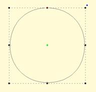
Start with a circle and draw a Breakline.
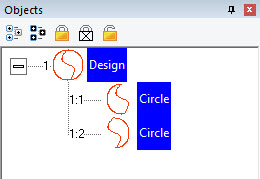
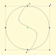
Cut the object with the Breakline. You can see it is now two
objects. 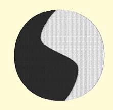
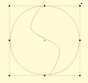
A Fill stitch has been added and colors chosen.
 Cut is a
path operation that lets you remove a part of a shape, in the form of another
shape. Think in terms of a cookie cutter. There is a base shape (earliest in the
sequence), your dough in this example, and a cookie cutter on top. Position the
cutter as you like, select the two shapes, and click the Cut button. The base
object will now have its shape adjusted to have the area under the cutter
removed.
Cut is a
path operation that lets you remove a part of a shape, in the form of another
shape. Think in terms of a cookie cutter. There is a base shape (earliest in the
sequence), your dough in this example, and a cookie cutter on top. Position the
cutter as you like, select the two shapes, and click the Cut button. The base
object will now have its shape adjusted to have the area under the cutter
removed.
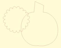
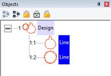
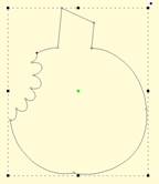
Here we use a couple shapes from the Library; the Pumpkin and
a Flower. Note the Pumpkin is the first object, which is the one that gets
operated on. Select both items and click the Cut button which gives the
appearance of a ‘bite’ being taken out of the pumpkin. Do we have rabbits in the
garden?
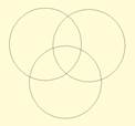
 This is a
more advanced operation where two or more shapes overlap one another, and you
want a new shape based on the area where the shapes overlap. The “AND” is where
this shape ‘and’ that shape both exist. It is used more for visual effects –
breaking a set of multiple overlapping shapes into even more parts. The results
of the AND operation are added after the last object used in the operation.
This is a
more advanced operation where two or more shapes overlap one another, and you
want a new shape based on the area where the shapes overlap. The “AND” is where
this shape ‘and’ that shape both exist. It is used more for visual effects –
breaking a set of multiple overlapping shapes into even more parts. The results
of the AND operation are added after the last object used in the operation.
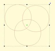
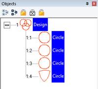
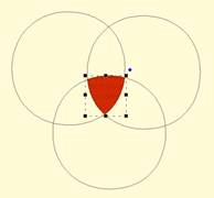
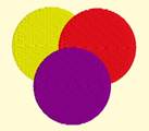
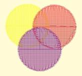
First, we merged three copies of a circle, then used the AND
button.
The result is shown as a red fill on the right.
Union
 When you
have two or more shapes that overlap, and you want to make a shape that
represents the entire outline of all the shapes, you use the Union button. This
could be effective for adding a border around a design. The new Union shape is
added to the design after the last of the shapes involved in the operation.
When you
have two or more shapes that overlap, and you want to make a shape that
represents the entire outline of all the shapes, you use the Union button. This
could be effective for adding a border around a design. The new Union shape is
added to the design after the last of the shapes involved in the operation.
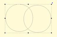
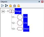
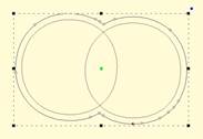
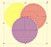
Two circles have been merged together on the left. Then the
Union button has been used to create the third object, a ‘Union’. The image on
the right shows the union object having been inflated so that it surrounds the
original two circles.
Flatten
 When
importing vector art from outside sources, it will be unlikely that the shapes
are truly ready for use in embroidery. Often times in the creation of vector art
it is expedient for the artist to layer one shape on top of another. In graphic
arts, only the final visible items will have any impact on the result, so any
shape or any part of a is shape may be hidden without consequence. In
embroidery, those shapes, as they exist, will be used. This means there will be
a tremendous amount of overlap. The Flatten command clips the shapes against
each other so that only one top layer remains. Remember that registration issues
will occur when you sew these objects, so you will likely need to do some
editing.
When
importing vector art from outside sources, it will be unlikely that the shapes
are truly ready for use in embroidery. Often times in the creation of vector art
it is expedient for the artist to layer one shape on top of another. In graphic
arts, only the final visible items will have any impact on the result, so any
shape or any part of a is shape may be hidden without consequence. In
embroidery, those shapes, as they exist, will be used. This means there will be
a tremendous amount of overlap. The Flatten command clips the shapes against
each other so that only one top layer remains. Remember that registration issues
will occur when you sew these objects, so you will likely need to do some
editing.

On the left is a graphic created and saved as an SVG. The
middle is the import of the SVG – notice the artist used three circles to create
the design, which seems reasonable enough. If we make them all fills (and set
colors, if needed) as we have on the right, it looks okay…
…But there is a problem. The design on the left is shown with
3D off so you can easily see the overlapping stitches. Once we use Flatten, as
in the design on the right, we are closer to having something that will sew
without damaging our needle or machine.
Inflating / Deflating shapes
 Sometimes
you need a shape to increase or decrease in size, but be exactly the same
distance around all the lines of the original. This means the new shape will
have to change. A classic example of this is echo quilting, where, as the lines
of stitching echo out, the curves become less tight, and fewer details are
visible.
Sometimes
you need a shape to increase or decrease in size, but be exactly the same
distance around all the lines of the original. This means the new shape will
have to change. A classic example of this is echo quilting, where, as the lines
of stitching echo out, the curves become less tight, and fewer details are
visible.
Clicking the Inflate button on the Tool Pane displays the
Inflate dialog, which allows you to inflate selected objects and their holes as
needed.
When inflating or deflating, the object selected will change.
Thus, if you wish to have the original shape retained on the page (for some
other part of the design) you should copy and paste it before inflating. See the
next section, ‘Automatic Outlining’ for an example use of inflation.
 Automatic
outlining will create a shape that surrounds any stitches on the design page.
This is useful when creating stitches that will add to an existing embroidery
design that has been merged onto the page.
Automatic
outlining will create a shape that surrounds any stitches on the design page.
This is useful when creating stitches that will add to an existing embroidery
design that has been merged onto the page.
Automatic outlining can also be used to create an object hole.
The purpose for this is for quilting designs. You can merge a design or create
an interior design with objects, then make a new outline in some larger shape,
for instance a quilt block, or your hoop. By adding a hole to that shape, in the
form of the current stitches on the page, you can create a stipple, or an echo
perhaps, that will surround those stitches and fill the block.
The automatic outlining can be combined with Inflation to
allow room around the stitches, for quilting or other purposes. For example,
there is a feature elsewhere in the platform that automatically creates
knockdown stitches for sewing on terry by first creating an automatic outline,
then inflating it slightly, and adding a light fill.
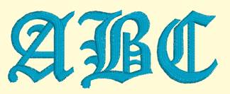
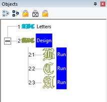
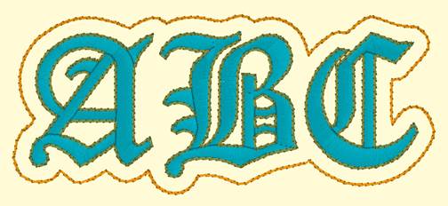
Here’s a quick illustration in use, starting with a basic
monogram:
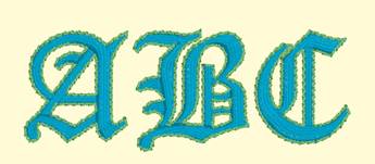
Now we will automatically outline it and set those new objects
to a backstitch, made green.
Let’s try a few more steps for fun:
Copy the outlines that were created by the Automatic Outline
tool:
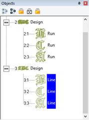
So, you should see this.
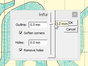
Use the Inflate button  to create echoed outlines of the letters.
Note the ‘Remove holes’ option is turned on. We are using a 5mm inflation.
to create echoed outlines of the letters.
Note the ‘Remove holes’ option is turned on. We are using a 5mm inflation.
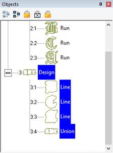
Add a Union. Next, delete the individual ‘Line’ objects, as we
won’t need them anymore.
Select the Union and use the menu
‘Create->outline->delete holes.’
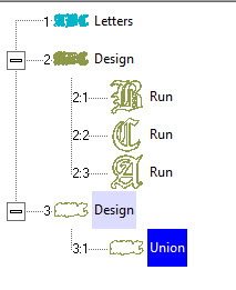
Now add a run to the Union, change style, color, etc.
Publishing
When you want to create your own art and use them within other
designs, as motifs or embossing patterns, you can ‘Publish’ them in several
ways, including the creation of a .BX install-file which lets you share your
work with others.
Motifs are used in Motif Runs and Motif Fills. The motif
itself is a design, and can contain any number of Manual, Run and Satin objects,
although usually a motif is a singular Manual stitch object. Naturally, a motif
cannot contain another motif.
Motifs run left-to-right, by convention in the system. They do
get reversed when needed during a fill, but we start with a normal orientation.
A motif’s first point and its last point should line up – or rather, they will
when used so you might want to consider that as you draw one.
Motifs use the vertical position of the initial and final
points as a baseline, like a letter would. The baseline is how much above and
below the line the motif will sit.
Manual points are mostly used in motifs, especially since Runs
will calculate, and the points where a needle will land are unpredictable when
the user is in control of the size. This is doubly true when going around tight
curves, where small changes in size will very much affect the position of the
stitches.
You can use satins to make a motif, and the satin will
generate for the size used in the Motif run or Motif fill. It is generally not
needed to use any underlay in the satin, although you can.
Normal motifs are fairly small, typically 2-4mm, so as to be
used in a Motif Fill with a reasonable number visible, but they can be large, if
warranted. You may want to make a motif that represents a particular client
logo, and embed that in the background of a fill in a larger design.
When storing motifs, you will be saving them on your system
for use in the future, but when they are used within an object, they are also
stored in that object. This means that if you edit the motif, the object won’t
be updated – you’ll need to remove that motif from the object that’s using it,
and re-add the new version.
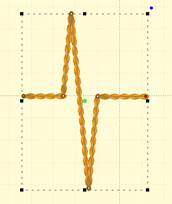
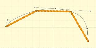
Let’s create a motif by drawing a shape and setting its type
to Manual. Note the first and last points are on the baseline.
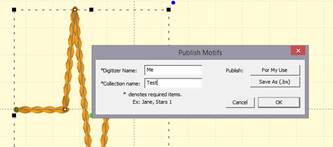
Now we can publish it (along with any other designs on the
page). Click ‘For My Use’:
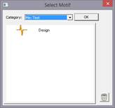
Now, let’s start a new Motif object. Click Add on the Motif
property and select the motif:
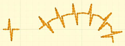
The motif, along with the result:
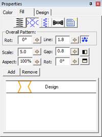
Creating Emboss Patterns
Embossing patterns can be either open or closed shapes, but
they will be used differently depending which they are. Open shapes are used as
repeating carving lines in a normal fill.
Closed shapes will have the fill stitches that lie internal to
the shape removed, unless that makes for an extra-long stitch. The effect of
closed shapes in a fill is that of satin areas within the fill, and those
provide dramatic relief from the fill stitching; almost a trapunto effect.
In order to ‘see’ more of the embossed pattern, keep its size
within the realm of your stitch length or smaller – typically 3.0mm - 5.5mm.
Embossing patterns are done with Line objects, as stitches
have no effect in the design. Also, you do not have to worry about transits,
overlap, and color or anything but the shape that is your desired result.
Emboss patterns are shapes that intersect the existing
stitches thus causing a needle-penetration. When the shape is parallel to the
stitches, it may not intersect; hence you can have sides of your shape that do
not create stitches. This is usually overcome by adjusting the inclination angle
a little bit, or rotating the emboss pattern, so that more intersections
occur.
Keep in mind what your emboss pattern will look where its
pattern will set next to a copy of itself; the design’s right edge shape will
interact with its left edge.
When storing emboss patterns, you will be saving them on your
system for use in the future, but when they are used within an object, they are
also stored in that object. This means that if you edit the pattern, the object
won’t be updated – you’ll need to remove that pattern from the object that’s
using it, and re-add the new version.
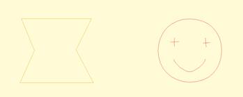
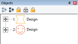
Let’s go through the process. Here we have drawn some line art
in two designs.
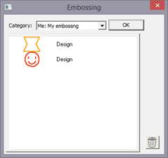
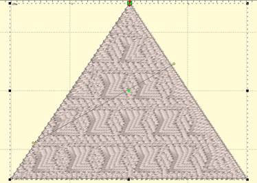
Next, we have a shape with a fill, and we’ll add an
embossing:
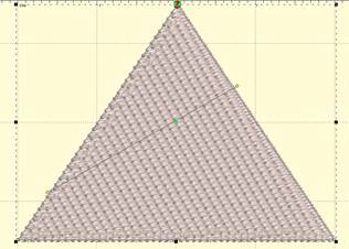
Notice the angle of inclination to cause more intersections in
the result:
Artwork drawn in the program can be exported as a vector file
in .svg format and for popular cutting machines. Use the menu ‘File->Export’
to save the artwork. This is not the same as the applique functions to save
cut-files (located on the Applique tab of the Color Window). Those outlines are
processed to directly cut an applique. The files saved when Exporting are the
objects as-drawn.