 (Level 3 shown)
Drawing is the main bit of work used to create a design. This section will let you know about various drawing methods.
(Level 3 shown)
Objects are usually shapes called “outlines”. The outlines are created by you, the user, drawing on top of a piece of artwork, importing a piece of artwork called a “vector file” or with the assistance of a Magic Wand (if you prefer not to create the shape yourself). An object’s outline may also contain one or more “holes,” also interchangeably called “voids.”
Objects will usually contain stitching of a certain kind, for instance a satin-stitched column.
The outlines are shaped using points on the shape called “nodes.” There are different kinds of nodes, and there are many things you can do with nodes to change the shape of the object. When you click on a node, you are highlighting it and its appearance will change to show that highlighted state. When the program sees that you have highlighted a node (or nodes) it will change what it does with your input based on that fact. For example, using the ‘delete’ key on an object that has no nodes selected will delete that object. However if you have selected nodes, then the delete key will delete those selected nodes.
Note: You do not need to switch modes to reshape an outline. You click an outline node to highlight it. If you wish to work with the object as a whole, either ctrl-click the highlighted node, or click off the object and then back on it. When none of an object’s nodes are highlighted, you are able to move and re-size the object using the handles that appear.
The underlying implementation of graphics in the platform uses Bezier curves, named after the man who first made use of them to design car bodies. Why do we use them here? Because the world has adopted these annoying-but-useful little curves; and all drawing packages, CAD packages and design software understands them, so there are a lot of people who have been trained in their use. Are there better solutions? Well, yes, but let’s not get into that right now, lest we upset the Math Police.
The idea of a Bezier curve is fairly simple. You have a start point and an end point, and a curved line that runs in between them. If you have a series of these, you can draw any kind of shape. The fun part is that the curve between the two endpoints is controlled by two ‘Handles,’ one connected to each node. In a simplified way, the first handle (which is connected to the start point) will determine how the line will curve as it takes off from the start. Likewise, the second handle will determine how the line comes in to the end point.
The benefit to embroiderers using these curves is scalability; Size does not matter. So if you make a Run stitch object using a curve, those stitches will generate nicely on that path at virtually any size, and the sewn result will be a nice clean curve even when made large.
 When
creating and editing outlines for shapes, you are always creating a Bezier form.
For beginners who are inexperienced with Bezier there exists an option to work
without “handles,” both when inputting a shape and when editing a shape. When
the Bezier handles are hidden on an object, you can edit the outline by moving,
adding and deleting nodes. This type of outline is known as a ‘spline’. The
limitation is that you cannot change the shape of the curve between outline
points. That is where the normal Bezier handles come in. You can switch any
object at any time between spline and Bezier, just be aware that when you go to
spline, your edits between nodes will be lost. Generally we always recommend
that you learn the Bezier and we have made every attempt to ease you into
that.
When
creating and editing outlines for shapes, you are always creating a Bezier form.
For beginners who are inexperienced with Bezier there exists an option to work
without “handles,” both when inputting a shape and when editing a shape. When
the Bezier handles are hidden on an object, you can edit the outline by moving,
adding and deleting nodes. This type of outline is known as a ‘spline’. The
limitation is that you cannot change the shape of the curve between outline
points. That is where the normal Bezier handles come in. You can switch any
object at any time between spline and Bezier, just be aware that when you go to
spline, your edits between nodes will be lost. Generally we always recommend
that you learn the Bezier and we have made every attempt to ease you into
that.
Note: If you want to quickly reshape a Bezier curve but don’t understand the handles, we have added a feature that lets you drag on the outline, between two nodes, and the outline will follow your mouse, adjusting the handles automatically. This is also very handy when you want to quickly draw with a very minimum of nodes, (very good for re-sizing later).
‘Nodes’ and ‘Knots’ mean the same thing as used here, and that is they refer to the outline points that are drawn and selectable.
Some things you can do with nodes on an outline:
•Select a node by clicking on it.
•Edit nodes by dragging them around.
•Add nodes by double-clicking where you want one to appear, and you can double-click a node to remove it.
•Drag around a set of nodes, in which case you will select all the ones in your “lasso”.
•Right-click while nodes are selected and change properties and do other things with the outline.
 When
a shape is drawn, it goes from one node to another. It can either form a
straight line to the next node, or it can form a curve going ‘through’ that next
node on its way to the one that follows. The advantage of curves is that when
you scale the design up in size, the result is a nice smooth outline. If you
draw with all ‘lines’, as many have done in the past, you are severely
restricting the useful size of the outline you are creating. For this reason, we
normally draw with curves, and you can switch to a line as you enter points (for
example by holding the ‘ctrl’ key) or you can do it after the design is
created.
When
a shape is drawn, it goes from one node to another. It can either form a
straight line to the next node, or it can form a curve going ‘through’ that next
node on its way to the one that follows. The advantage of curves is that when
you scale the design up in size, the result is a nice smooth outline. If you
draw with all ‘lines’, as many have done in the past, you are severely
restricting the useful size of the outline you are creating. For this reason, we
normally draw with curves, and you can switch to a line as you enter points (for
example by holding the ‘ctrl’ key) or you can do it after the design is
created.
If you think about it, straight lines are not ‘natural’ except in math; only people create things in the real world with perfectly straight lines. So curves and cusps are very useful, unless of course you are making a geometric design.
Notes: ‘Curved’ and ‘Line’ node types refer to the path coming toward the node. The path leaving the node is controlled by the following node.
A ‘Cusp’ allows two curves to go in different directions away from a common node, whereas a ‘Curved’ node creates a smooth line through the node, transitioning between the two curves smoothly.
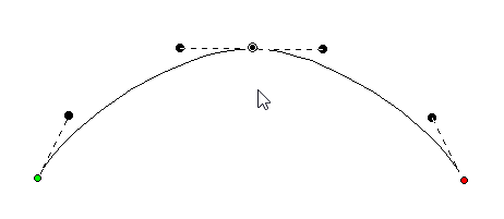
Here is an example of a curved node in the middle, and a hard point at the end. See how the path is a flat line going toward the final point. The path shape is defined by the node it is going toward.
A straight line does not have handles. There is no need, as there is nothing to adjust. If you want to make it curve, change the node type.
On any path, there is a green node that indicates the start, and a red node that indicates the end of the path. A closed shape will naturally have the end positioned over the start, so it appears red.
If there are only two nodes in a path, you have a section. The section can be a line or a curve, depending on the later node type. If you add a third node at the end, and that one is also a curve, now you have a choice as to what to do with the curve as it passes through the middle node. It can be smooth-flowing, in which case the curve looks like one continuous line. Or, it can be disjointed, making two distinct curves, in which case it is called a ‘Cusp’.
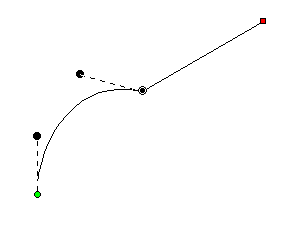
This image shows a selected curved node in the middle of a 3-node path; its handles coming in and going out indicate the travel of the stitches. The handle coming in is in a line with the handle going out, thus the curve is quite smooth at the node – it is almost like the node is not there, other than to direct the path.
Remember, smooth curves are created by at least three nodes: an initial starting node, a middle node that the curve runs through, and an ending node. You can click a long smooth curve that runs though as many nodes in the middle as you want, but naturally there’s always a start and an end.
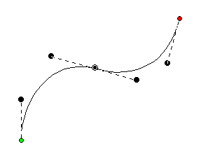
The alternative to a smooth curve is to have a node that comes ‘in’ from one direction, but leaves in another. This is a ‘cusp.’ Cusps are important, as they make the hard turns where curvy bits intersect – such as the top of a heart or in shapes of leaves, or almost anything in nature.
 A
cusp allows you to have two curves come together on either side of a point. For
instance the apex in the top, center of a heart-shape is a cusp. Traditionally
digitizers would make a curve that falls just short of the cusp and then make a
line to the cusp, and then they would begin a new curve going off to the other
side. This has the negative effect of that hard line being visible, especially
when scaled. It also produces a needle penetration where it isn’t needed. We’ll
discuss more on this later.
A
cusp allows you to have two curves come together on either side of a point. For
instance the apex in the top, center of a heart-shape is a cusp. Traditionally
digitizers would make a curve that falls just short of the cusp and then make a
line to the cusp, and then they would begin a new curve going off to the other
side. This has the negative effect of that hard line being visible, especially
when scaled. It also produces a needle penetration where it isn’t needed. We’ll
discuss more on this later.
Use nodes where the path switches from turning left-to-right or vice versa. And then when turning, place a node at the ‘widest’ point in the turn if you need an additional node. This will yield the fewest number of nodes needed to make the shape. Remember you can add nodes later, or adjust the curves, if you need to refine the shape.
It is good to use minimal nodes to complete your shape, and then go back and edit the curves to get the shape you want. The result will be a nicer object shape and better embroidery. It takes practice, but you’ll find that you can quickly analyze a shape and create it in very few clicks, and then the edits required will be much easier.
Normally in graphics a “Closed” shape or outline means that its start and its end meet up visibly. A shape that is closed can contain stitches within, and can also have “holes.”
 When
drawing a shape for embroidery, you may wish to have the end-point meet up with
the start-point without calling the shape “Closed.” For this purpose, there is a
button on the tool pane that lets you specify that a shape is closed or not.
Only closed shapes can contain holes.
When
drawing a shape for embroidery, you may wish to have the end-point meet up with
the start-point without calling the shape “Closed.” For this purpose, there is a
button on the tool pane that lets you specify that a shape is closed or not.
Only closed shapes can contain holes.
You can open an outline by clicking the ‘Close/Open Outline’ button up. You will not see a change in the shape, but you can now move the head and tail nodes away from each other. The tail node will be red.
If you have a node selected when you open the outline, that node becomes the new head/tail of the outline.
Oftentimes a drawing needs to be perfectly symmetrical. In this case the first side of the drawing can be made, and the completion can be done automatically using the menu Create>Outlines>Complete Symmetric. This will also close the outline.
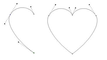
Left: First half drawn, Right: After Complete Symmetric
The Point Input method is the most commonly used method, and for most people, it is the easiest. Click the Point button in the Tool Pane and then start clicking along the line you wish to make.
 As
you create your shape, you can create curved nodes with a normal left-click,
line nodes are made by holding the ‘Ctrl’ key during a left click, and cusps are
made by holding the ‘Shift’ key down during a left click.
As
you create your shape, you can create curved nodes with a normal left-click,
line nodes are made by holding the ‘Ctrl’ key during a left click, and cusps are
made by holding the ‘Shift’ key down during a left click.
You can use the ‘backspace’ or ‘Delete’ to remove points you have entered. You can cancel the drawing using the ‘Esc’ or ‘Escape’ key.
When you have completed your shape, you can end it by right-clicking. If you wish to end the shape and also close the outline at the same time, hold the ‘ctrl’ key while right clicking.
While entering points along the outline, you do not need to worry about the Bezier handles – they are created for you using some ‘reasonable’ values. Once you have created your shape, if you want to adjust the handles, you can. Or you can ignore them entirely if you prefer. We’ll talk about that shortly, in the ‘Editing Outlines’ section, subtitled “Working as Spline/Bezier”
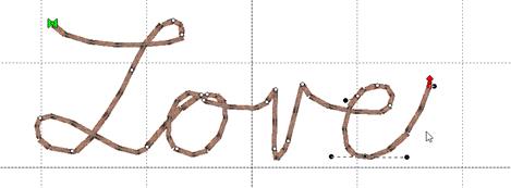
 This
sounds like the most fun input method, and it is, but it is far from accurate.
The freehand input lets you doodle. You hold the mouse down and drag around.
Where you went gets smoothed out and turned into a curving path. You can click
for a line to a point, and then drag along some more. You can drag and release
any number of times to create lengthy and intricate paths if you wish.
This
sounds like the most fun input method, and it is, but it is far from accurate.
The freehand input lets you doodle. You hold the mouse down and drag around.
Where you went gets smoothed out and turned into a curving path. You can click
for a line to a point, and then drag along some more. You can drag and release
any number of times to create lengthy and intricate paths if you wish.
This is useful in practicality only with the Run stitch type. Drawing freehand on a computer requires practice, and the more fluid your input is, the better the result will be. Do expect to spend some time cleaning up your handwriting!
As with other input methods, right-click to end your input. Holding the ‘Ctrl’ key when right-clicking will close the shape.
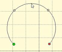
 When
you want to create a curve that is perfectly circular, the Arc input can help.
This input uses three points, clicked with the mouse, to create the arc. The
first and second inputs should be on the arc that you want to create. After the
second click, moving the mouse will draw a circular arc between those first two
points, running through your mouse cursor. Once you have the desired arc, click
the mouse a third time, which ends the arc input.
When
you want to create a curve that is perfectly circular, the Arc input can help.
This input uses three points, clicked with the mouse, to create the arc. The
first and second inputs should be on the arc that you want to create. After the
second click, moving the mouse will draw a circular arc between those first two
points, running through your mouse cursor. Once you have the desired arc, click
the mouse a third time, which ends the arc input.
This program, like most drawing programs, allows Bezier forms to take up to 90 degrees per node. If the circular arc you create goes around more than a quarter of a circle, multiple nodes will be added.
You can edit the nodes which the arc input creates as you would any other.
 The
Shape button activates a mode that creates a shape by dragging the mouse on the
design page. The down-pointing arrow next to the image on the button makes the
shape selection panel appear.
The
Shape button activates a mode that creates a shape by dragging the mouse on the
design page. The down-pointing arrow next to the image on the button makes the
shape selection panel appear.

To change the shape, click on a button to select the shape that the tool will create.
Click the shape button, and then drag on the design page. The size and orientation (rotation) of the shape is controlled by the length and direction of your drag. Let go of the mouse button and the shape will appear on the page as a new object.
Shapes that might be useful in rectangular proportion, such as rectangles and polygons, will follow the drag from the top, left diagonal corner to the bottom, right corner. If you wish to make things perfectly square, hold the Shift key down while dragging.
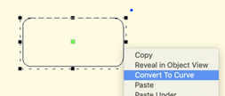
Some shapes have properties to adjust details of the shape, such as corner roundness, number of corners, density of a spiral, etc.
Shapes, as objects, have these special properties for the life of the shape and can be adjusted at any time. The shape’s outline can be edited by converting the shape to an outline. Right-click on a selected shape and choose ‘Convert to Curve.’
Whether it is used as a shape or converted to a curve, the object can have stitches applied.
 The
professional graphics industry has adopted this method of input and it takes
getting used to. Select the Bezier Input method using the button on the Tool
Pane. To begin, click and drag. This will create an initial Node and a Bezier
handle. The next time you click and drag, you will be creating the points needed
to complete a Bezier curve section, and also begin the next one.
The
professional graphics industry has adopted this method of input and it takes
getting used to. Select the Bezier Input method using the button on the Tool
Pane. To begin, click and drag. This will create an initial Node and a Bezier
handle. The next time you click and drag, you will be creating the points needed
to complete a Bezier curve section, and also begin the next one.
If you simply click, you will create a flat curve – a line.
To create a cusp, hold the ‘ctrl’ key down when you click and drag.
Right-click to end your input. Holding the ‘Ctrl’ key when right-clicking will close the shape.