StitchArtist is a program designed to allow embroiderers to
create stitch designs from scratch using existing artwork or by ‘drawing with
stitches.’ It has been described as an object-based digitizer. You draw and
control the shapes, set the stitch type and properties, and StitchArtist
generates stitches for you. When you want to create stitches, that’s what it
does.
StitchArtist comes in levels that suit different skill level
embroiderers.
Note: Each topic in this manual may
have notes for different levels. This allows for continuity in the learning
process. As you progress, you can purchase additional levels whenever you are
ready.
Level 1 is designed for a hobby embroiderer who needs to be
able to create stitches without going into debt or spending much computer time.
Level 1 offers a limited set of stitch types and, more importantly, properties
for those stitches, so that the user can simply ‘create.’ Typical projects for
Level 1 are applique designs, running stitch designs and simple filled shapes,
backgrounds or unifying elements for design compositions etc. It is not designed
for logo work or publishing, unless you’re working with applique.
Level 2 includes Level 1 and is designed for basic skills
training for those who would like to create more sophisticated designs, as well
as a basic set of tools for logo creation. It will allow the user to learn a
wide cross-section of stitch types and properties, and have enough freedom to
create virtually anything.
Level 3 includes Level 1 and Level 2 and is designed for
someone who either loves to create designs or works commercially in the
embroidery field. This level includes advanced items such as QuickStyles, adding
user-created motifs and designs, graphical operators such as Reconstruct,
Outline Stitches, Inflate, Cut, AND, Union and Break, extended Vector support
and more.
Note: Illustrations in this manual are shown with Level 3
enabled unless otherwise noted. Feature differences in other levels will be
discussed in the text.
StitchArtist is not an attempt at fully automatic design
creation. It will not attempt to ‘convert an image’ into embroidery; It does not
contain photo-to-stitch for example. These are all reasonable tasks, but are not
the same as what StitchArtist is.
It is also not a ‘customizing’ or ‘editing’ program for the
manipulation of existing embroidery designs. You may load designs so that you
can add stitches to them, but they are not alterable in most ways.
Embroidery designs have been created with computer programs
since the late 1970’s. The hardware used by artists at the time came from the
CAD/CAM industry (Computer Aided Design/Manufacturing) and consisted of a CAD
“digitizing” board (like an architect desk) and a mouse-like ‘puck.’ As no one
thought to change the CAD term, the word “digitizing” has been with us in the
embroidery craft ever since. We prefer the term “Design Creation” though
for two reasons: 1: Because it really is more accurate. And 2: Because the
term “digitizing” carries negative connotations of difficult-to-learn software.
Therefore “Digitizing” and “Design Creation” are interchangeable in this manual;
however, our product is a change in the user interface, and is easier to use.
Just wait, you’ll see.
Design creation is a two-fold learning process. First, there
is the software. That is the set of buttons and sliders that make objects to be
stitched. That’s pretty easy to learn, especially for anyone who understands
drawing programs or even has general computer skills. Whereas digitizing
software in the past had been developed in its own little world, and the
graphics programs went their own ways, the two are now converging with similar
tools and operations in both. Do not be misled into thinking that embroidery and
graphics are at all similar though, as designers can get away with all kinds of
things in graphics that simply are not possible in embroidery. The level of
sophistication in an embroidery creation program is much higher than a graphics
program, generally speaking.
That brings us to the second and more difficult part of the
learning curve – the knowledge of embroidery itself. Embroidery involves thread
and fabric. Both are flexible, usually stretchy to some extent and operate
differently in different combinations. In graphics you can do things however you
want: In any order, at any place, or jump from point to point without regard.
And the result will always look the same. With embroidery all those assumptions
are false. You need to understand which stitches will go down first, and why
they go there, and you need to really think about where the machine is going to
go as it stitches the design. Generally, there are three areas of thought that
need to be part of your process when you create a design:
•
The material, thread and project combination. This dictates certain items
such as the amount of coverage you need, the maximum number of stitches within
an area that can be added to the fabric before it puckers, and how it will be
stabilized so as to mitigate somewhat the inherent limits of the fabric.
•
The path the machine will take as it creates the design. You don’t want
to leave thread trails all over, and you don’t want to have to cut those either.
Even if the machine does that for you, you still have to spend the time on that
process. And if a design always sews in a given direction, you wind up pushing
the fabric around so much that the later stitches won’t align or ‘register’ with
the earlier ones.
•
The types of stitches used. This is the topic that is easily
understood, but can take a lifetime to master. The basic stitches are pretty
obvious, but the quality of the output comes from clever usage and combinations
of elements.
This manual covers the usage of the program itself, and
attempts to interject some knowledge of the embroidery process as well. However,
we very much recommend the reader take educational programs on design creation
from others. There are a number of wonderful educators for digitizing in the
marketplace, and their fees are generally well worth the knowledge you will
gain. With respect to those instructors, please humbly accept that any
differences you find herein with regards to your teachings, are not intended to
be the ‘only way’ someone ought to do something, nor necessarily the ‘best’
approach, but perhaps is what we ourselves are comfortable teaching. We all have
our own styles, and those differ from time to time.
If you have never embroidered before, take some time to learn
the use of your machine and the basics of embroidery. Your local sewing machine
store will have classes that you can attend to help you get going. We must
assume for the purposes of this manual that you understand the ordinary hobby
aspects of embroidery – what a hoop is, what stabilizer is, what a ‘design’ is
etc. Hopefully you have at least stitched something successfully.
You do not have to be an artist. Really -- let’s say it again
--you do not have to be an artist.
The reason is that embroidery creation is more of a
‘color-by-numbers’ process. You may be an artist, and that’s great. You can even
create your art within the program. However, the process of laying stitches on
top of your art or image is a mechanical, methodical and logical process,
provided that the art is suitable for embroidery. And there too is a reason why
we ask that you have at least done embroidery – it will provide you some insight
as to what’s possible with embroidery, and what simply isn’t. Naturally an
artist can alter a complex image to be more suitable for embroidery, and a
person with some experience creating designs may be able to do that intuitively
as they work. It all comes from the learning process and involves much trial and
error along the way. You won’t learn to paint overnight, nor learn to play
Chopin the first time you sit at a piano, so please don’t expect to be creating
complex designs well the first time either. But with a bit of persistence,
creating designs is a much faster and easier learning curve than those other
endeavors, and you can begin with simple things and start sewing in practically
no time.
Reminder
about Levels: Illustrations in this manual are shown with Level 3 enabled
unless otherwise noted. Feature differences in other levels will be discussed in
the text. Some sections have information pertaining to multiple levels. We have
indicated the minimum level for which the text is relevant. Where practical, we
have added higher-level information toward the ends of sections.
 The
interface in StitchArtist is different in some respects than programs that have
come before, especially digitizing software. We’ll define all these terms as we
go, but if you’re familiar with them already there are some things you should
know now…
The
interface in StitchArtist is different in some respects than programs that have
come before, especially digitizing software. We’ll define all these terms as we
go, but if you’re familiar with them already there are some things you should
know now…
When creating embroidery, you normally will be doing several
types of tasks:
1.
Loading artwork as the basis for the design
2.
Creating stitch-generating “objects.”
3.
Editing the “shapes” or “outlines” of those objects.
4.
Editing the “properties” for those objects.
5.
Moving objects around on the design page.
6.
Sequencing objects for sewing order.
7.
Adjusting the “entry and exit points” for sewing objects.
8.
Colorizing objects.
In StitchArtist these different types of operations do not
require any program ‘modes’. Generally speaking, there are only two modes that
you’ll run into during design creation: The normal ‘Selection’ mode when the
program starts, and the ‘Creation’ mode that you’ll use while creating the
designs.
You will not need a separate tool to reshape the outline of
designs, nor need to switch modes to size or move objects. All the tools for
design creation are accessed from either the ‘Create’ menu or the ‘Create’ Tool
Pane, which is shown using the ‘Create’ button on the main toolbar.
All selected objects have their properties adjustable at all
times, and the properties can be set on any number of selected objects
simultaneously, causing immediate generation of the selected objects.
There are also virtually no “Apply” buttons or ‘Enter’-key
requirements – stitch generation is automatic and immediate.
There are a number of features in the platform that are
consistent across the products including the Navigation HUD (a compass rose in
the top, right corner of the Main Window), the Zoom Slider, the Edit Menu, Zoom
keys, etc. Please review these areas in the program help so that you’ll know the
basic navigation of the program.
Design Pages, Designs and Objects
Objects are usually shapes that have stitch types and
properties associated with them. The object may for instance be a Run, or a
Satin Column or perhaps a Fill.
Objects can contain lots of information: Outlines, holes,
inclinations, breaks, images, stitches and colors. Thus, a single object could
contain an applique – the shape of the applique, a picture you want to print
cropped in the outline, the stitches that are generated to sew the applique and
the colors for the position, material and topstitch sewing, and even more. We’ll
discuss all that separately, so please keep reading.
Designs are groups of objects that are collected together.
This might be an individual design that you want to sell, or a smaller piece
that you’ll reuse as an element in other designs. Designs let the user work
within a section of an overall composition without being encumbered by the
whole. This is similar, but not equivalent to, a term used in some graphics
programs as a “layer.”
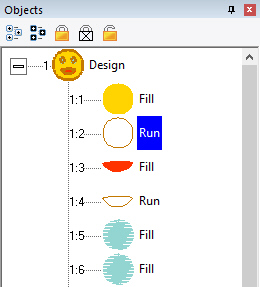
When observing the relationships between designs and objects,
see that the Object View, normally docked on the right of the program screen,
has at its ‘root’ level the designs, and when you expand a design, you’ll see
the individual objects that compose that design. If you select a design, by
clicking on it in the Object View, you will be selecting all the objects
contained in that design as well. If you select all the objects in a design,
selection of the design itself is optional. This is useful for copy/paste
operations.
When creating new objects, you have the ability to choose
where they go – into which design, and even where in that design they are
created. We’ll talk more about that in the ‘Creating Objects’ section.
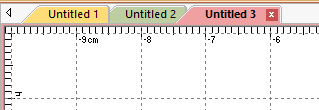
The top level of the program uses what is called a Design
Page, which is related to a document or file. The Design Page is stored as a .BE
file on your computer, and can contain any number of designs, each composed of
any number of objects. You can have as many open Design Pages (or documents) as
you like, and each is represented by a tab at the top of the main view.
Properties
The interface has a Property Page, usually visible on the
lower right part of the program window. The size of the Property Page can be
adjusted using the splitter bar that lies at the bottom of the Object
View. You can also drag the splitter bar that lies on the right of the
Main View if desired. For general interface adjustments, please review the user
interface section of the program help.
When you select objects, their properties are shown as tabs in
the Property View. If you have more than one object of a given type, the
properties of the first selected object of that type are shown.
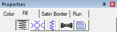
The controls for the properties mostly exist in five
forms:
1.
A set of buttons that let you choose which properties you are adjusting.
2.
A drop-list that lets you select from a set up options.
3.
An editable text field that lets you adjust a value.
4.
A pop-up slider that lets you set an adjacent text field by dragging its
value.
5.
A check box that lets you turn a property on or off.
If you adjust a property, all the selected objects of that
type will have that specific, and only that one, property adjusted. Having
adjusted the property, the stitches will generate automatically. You should see
the change in the stitches of the object immediately.
Color is a property of an object. Objects have one color each,
except for appliques, which by definition need to stop the machine. When
exporting stitches, objects of the same color that follow each other will not
cause the embroidery machine to stop unless there are applique steps
involved.
When no objects are selected, all of the colors for the page
are visible and changeable. To change a color, simply click on it in the
list.
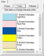
The Color Properties window.
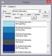
Thread line selected
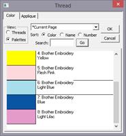
Palette selected
Design creators often need to utilize a palette of given
colors. Sometimes these represent a customer’s job requirements, and other times
it is merely a matter of needle assignment for the embroidery machine. You can
create palettes at any time using the menu Utility->Threads… And you can
choose to use any palette as you adjust the color properties.
You can also create a palette on the fly while creating your
design. If you wish to switch to an already-used color on the current page,
select the ‘Palettes’ button in the color window and you will see in the list,
“*Current Page.”
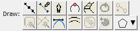
The Tool Pane
The tool
pane is located below the main toolbar. When you click the toolbar button to
create stitches, you’ll see this tool pane, which is divided into sections.

The first section is used to bring existing images or artwork
into the program. You can load a raster image (Bitmap, Jpeg) or a Vector image
(Metafile, Adobe Illustrator) or even use a TrueType font as artwork for your
creation.
The next section contains view and mode options. You can hide
the background images or the stitches while you are creating your designs. You
can also re-sequence the objects in a mode that lets you click on them one after
the other on the Main View.
The drawing tools are next. These let you create shapes, open
and close outlines, add inclination and carving lines, etc.
The Stitches section is used to apply stitch types to selected
objects.
The Paths section is used by illustrators to convert images
into useable embroidery shapes.
When using tools such as the Magic Wand, another section
becomes visible as needed to allow for adjustments to the current
process.
Sometimes you want to pan the screen – in other words, move it
around – while not changing your zoom, or using the scroll bars. The easy way to
do this is with the spacebar key. Hold the spacebar down, your mouse cursor will
change to an image of a hand, and then drag the screen with your mouse.
While drawing shapes or dragging during edits, it is quite
common that you will need to move to part of the image that’s not on the screen.
Rather than use the scroll bars, which you can, you can also move the mouse to
the edge of the main window. When you get within a few pixels of the edge, the
view will scroll for you in the direction of the edge your mouse is over. When
not dragging, the screen will not scroll automatically.
Sometimes you want a reference line that is not on the main
grid. Place your mouse inside the area of either ruler – horizontal or vertical
at the top or right edge of the Main View. Then, drag, using the left mouse
button and you will then be setting a guide line. You can drag these guide lines
wherever you like, and if you drag one back to the ruler area from which it
came, it will be removed from the page.
 Sometimes
the view of the artwork makes it hard to see what stitches you have created. You
can quickly toggle the images on and off using the Image Toggle button on the
tool pane or using the ‘b’ key.
Sometimes
the view of the artwork makes it hard to see what stitches you have created. You
can quickly toggle the images on and off using the Image Toggle button on the
tool pane or using the ‘b’ key.
The stitches are usually kept in view so that you can see what
they are doing. However, sometimes you want to see only the outlines, and hide
the stitches. This is done with the ‘Stitch View’ toggle button on the tool pane
or with the ‘n’ key. This is helpful especially when editing.
Note:
Stitches
are not in view while drawing or scrolling.
 The
Continuous View is used to see how items will connect when embroidered in a
continuous hoop, or as a repeated pattern. It creates a set of duplicate images
that let you see how your design will connect or interact with an identical
copy. The image is not an actual design – it is just an image for
reference.
The
Continuous View is used to see how items will connect when embroidered in a
continuous hoop, or as a repeated pattern. It creates a set of duplicate images
that let you see how your design will connect or interact with an identical
copy. The image is not an actual design – it is just an image for
reference.
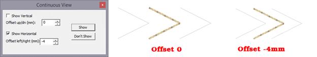
The offset setting allows you to
inset a repeated element, instead of the default, 0, which aligns the image of
the copy with the outer edge of the design.
Some digitizers advocate getting used to a particular scale or
scales while you are creating a design. This allows you to learn what a useful
distance in the real world will look like on-screen. The Embrilliance platform
has a Preference that lets you calibrate the display to a Real Scale (See the
program help on User Interface for details). Once you have done that for your
computer/monitor setup, it does not need to be done again.
To get to a particular ‘zoom’ level, use the number keys. ‘1’
is a 1:1 ratio of the size of things on-screen to the real world. 3:1 and 6:1
are popular as well. If you use the number key ‘0’ you will be zoomed to your
hoop.
Using a consistent set of scales is useful. Once you become
well used to seeing design work at those scales, you’ll be able to know what the
stitches will look like without having to sew them out. If you are zoomed too
far in, you will likely be creating more detail than the design will need which
slows the design creation process and can even negatively impact the sew-ability
of the design.
If you are editing a design, feel free to use the zoom slider
or other keys such as ‘A’ (All), ‘S’ (Selected) to work at a comfortable level.
Generally speaking, unless an object outline is very large, you should be able
to see the whole object on your screen while editing. Zooming in extra close can
be useful to make the nodes line-up perfectly, but that is not necessary for a
great design.
Note: If you have any objects
selected, using the “s” key is a quick way to center the Main View on them for
editing.
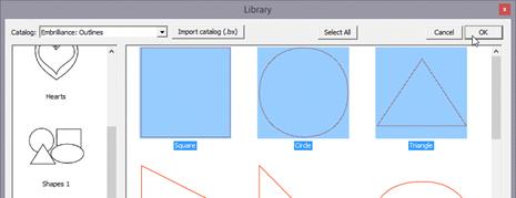
 The
Library button on the main toolbar will bring in design collections that have
been published in the platform. There are several collections included which
allow you to use them in your own work – saving you time in drawing these
shapes. When bringing in a library shape, the program uses the current page’s
view center and zoom level to determine where it will come in. Once it has been
brought in, you can size and place it as needed, even edit its outline, as if
you had drawn it yourself.
The
Library button on the main toolbar will bring in design collections that have
been published in the platform. There are several collections included which
allow you to use them in your own work – saving you time in drawing these
shapes. When bringing in a library shape, the program uses the current page’s
view center and zoom level to determine where it will come in. Once it has been
brought in, you can size and place it as needed, even edit its outline, as if
you had drawn it yourself.
The Library has been extended to include hundreds of outlines
that you can use with StitchArtist to make your own designs. They are even
royalty-free!
Working with Designs
Designs and objects will create themselves as you begin
drawing and as a result of copy/paste operations. But there are some options you
should be aware of.
Each design page, which is represented by a working file (.BE)
is selected using the tabs at the top of the main window. Each page can contain
any number of designs. Sometimes it is useful to break up your work into
discreet areas that can be managed as a unit. Designs are the mechanism for
this. For example, suppose you make a nice rose. Now you want a bouquet. You
could make the rose as a single design, and then place it in multiple positions
and sizes to complete your image.
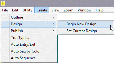
If you have no designs on the page, one will be created for
you when you either bring in artwork or begin to draw. However, if you wish to
switch to a new design to begin drawing a separate piece, you use the menu
Create->Design->Begin New Design.
If you are working back and forth between multiple designs,
when you draw new objects, you will need to decide where they go. To do this you
have options:
1.
Select the design in the Object View, and then use the menu
Create->Design->Set Current Design.
2.
Select an object in whichever design you wish to work, and begin drawing. Your
new object will appear in the sequence following the object that was
selected.
In computer graphics there are two basic ways to create an
image and those are called “bitmap” and “vector.”
 There are
buttons to allow you to bring in artwork from files. To use an image file such
as a .bmp or .jpeg as a backdrop for your design, click the “Image…” button.
There are
buttons to allow you to bring in artwork from files. To use an image file such
as a .bmp or .jpeg as a backdrop for your design, click the “Image…” button.
Alternately, you can drag and drop image
files, filenames, or simply have copied images from a web browser or other
program, then paste onto the design page.
Once you have selected an image, the program will
automatically begin a design for you (if you haven’t already), and place that
image as a new object in the design. The image is selected and can be scaled or
rotated, squished, etc. The images used for backgrounds generally are preferred
to be semi-transparent, and that is also set for you. You can do whatever you
like with the image at this point to help you begin creating stitch objects on
top of it.
Once you begin making other objects, the image itself will
lock into place. This means you will not be able to accidentally select or move
it while you are creating your design. You can still edit it by selecting it in
the Object View. There, you can even unlock it. Generally, once a stitch object
has been placed over an image, you don’t want it moving around.
Note:
The Image button works for
pixel-based images such as photos and scans. Files created using vectors are not
pixel-based images, and do not load using this function. See the section on
Vectors for information about loading those.
Bitmaps are also known as “raster” images, which might be more
technically correct though the terms today are used interchangeably. Bitmap
images are composed of different colored dots. Images such as photographs fit
into this category. Bitmap representations of art are the preferred type
to create stitches from; they come in as background images over which you will
create stitch objects.
When using a bitmap image, there is the issue of “resolution”
which refers to how many dots called “pixels” are being used. The more pixels,
the better the clarity of the image and fewer pixels make for an image that has
little stair-steps in it when you zoom in. One might think that more pixels are
better. However, the program has to do a lot of work while you are drawing your
design and an image with a lot of pixels makes it take that much longer to do
each step while you are working. So, it makes sense to use an image that is not
super-duper-hi-resolution.
When deciding what resolution, you want to use, or how many
pixels should be in the image, it is worth considering how that will match up to
the embroidery design itself. In an embroidery design the most common density of
a stitch is about 0.4mm or 4 stitch points. This equates to a resolution of 64
DPI (Dots Per Inch) and that means that a typical 4” (100mm) square design would
only need an image of 250 pixels on each edge. The normal smartphone will give
you thousands of pixels on an edge, so any photo today probably has more than
enough resolution for what you need.
We recommend, for simplicity, that you keep your image to
around 1000 pixels on either edge. You can go for more if you’re making a super
large design, naturally, but otherwise this is a good number. A lot of graphics
that exist on the internet are 1024x768 or 800x600 because these are common web
sizes. And those images have plenty of resolution for you to create embroidery.
If you are making a 14” design, you might want to bump that to 1500-2000 pixels
on the widest edge. But remember more is not always better.
Vectors (Level 2, 3)
 Vector
files are artwork themselves. These files are brought in as objects. The user
must realize that graphics files contain objects with outline weights
(thickness) and all sorts of color properties that are inapplicable to an
embroidery design. As such, when importing vectors, the outline and its color
are all that are brought in. For some designs, this saves the user the work of
having to re-draw the image.
Vector
files are artwork themselves. These files are brought in as objects. The user
must realize that graphics files contain objects with outline weights
(thickness) and all sorts of color properties that are inapplicable to an
embroidery design. As such, when importing vectors, the outline and its color
are all that are brought in. For some designs, this saves the user the work of
having to re-draw the image.
In addition to the Vector button, you can drag and drop .svg
files or filenames then paste onto the design page. In the case of copying from
a drawing program, many will simply put a bitmap representation on the
clipboard. This is often acceptable, as most digitizers redraw over the image
anyway.
Vector images are outlines filled with color – think of a
company logo, cartoon, comic or coloring book.
As vector images already have outlines in them, and embroidery
objects have outlines too, it might seem reasonable that starting with a
vector-based image is better for this purpose. You would have little to draw
because the art is already there for you. Simply set the stitch properties and
you’re done, right? Well, you can, and we do import them for that purpose,
but…
…In actuality that is rarely the case.
Vector artists can do things with their objects, such as
‘overlapping,’ which makes embroidery of the outline completely impossible.
Also, the shapes can be directly adjacent, which will leave gaps in embroidery.
And vector artists jump from color to color and back again very casually. You
don’t want to attempt this with embroidery. So, while the allure of using vector
files is there, it actually can take more work to make a vector-based image work
for you than simply creating objects over top of a bitmap image.
Another common problem using vector-based images is that of
the original source. There are a lot of clipart companies in the world, and they
offer their product in a variety of file formats. When an artist submits an
image that was created as a bitmap, the company then uses a program to
‘auto-trace’ the outlines in the image so that you, the customer, can get your
‘vector’ version of it as an EMF or WMF or AI file, etc. Those files are almost
universally the worst thing to use for the reason that they contain as many as
one hundred times the number of outline nodes as needed, and they are often
‘line’ nodes, which means the stitches that will be generated will have to stop
at each node.
Given these inherent difficulties, Level 3 has added features
that let you overcome these problems.
However, for all these reasons we suggest you always use a
bitmap picture - .bmp, .jpeg, etc. That is unless you yourself are the artist or
whoever is creating the vector files as the original format and have done so
with embroidery design in mind.
 TrueType
fonts exist as single-color outlines in your computer. As many logos began life
as a TrueType font, you may want to use one as the basis for your design. There
are many free-to-use fonts available on the internet, although some require
payment if you use them. Check the font’s license to be sure, especially in
commercial circumstances. For this purpose, let’s assume you have either
permission or freely licensed fonts.
TrueType
fonts exist as single-color outlines in your computer. As many logos began life
as a TrueType font, you may want to use one as the basis for your design. There
are many free-to-use fonts available on the internet, although some require
payment if you use them. Check the font’s license to be sure, especially in
commercial circumstances. For this purpose, let’s assume you have either
permission or freely licensed fonts.
When you select text in a given font, the computer provides
that in outline form. Each outline is given as an object. For example, the
lower-case letter ‘i’ will usually have two objects; one for the dot and one for
the stroke. You can use these outlines as stitch types anyway you want. You can
make them outline designs by applying a run, or you could use the art for satin
stitches. You could even make them huge and set them to a fill, cross stitch or
applique. It’s just a piece of art as if you had drawn it yourself.
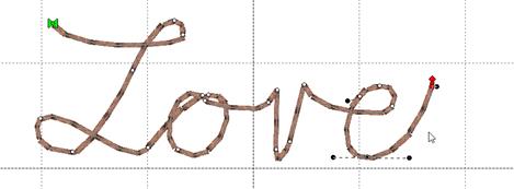
You may use the drawing tools in the program to create your
own art. There are enough tools there to do it, however, graphics packages will
offer more flexibility in terms of things like pen nibs and gradient colors, but
those are very different in embroidery when compared to graphics. Therefore, the
drawing tools in this program are geared toward stitch generation – you are
literally drawing with stitch-generating shapes, making you a Stitch
Artist.
As we explore the process of design creation, we need to get
some terminology out of the way. If a word stumps you while reading halfway down
a page, your brain will get stuck there and not retain anything else you’ve
read. So, let’s do some vocabulary, and at the same time, learn a few
things.
Objects are the building blocks of the design. There are
different types of objects, and their order or “sequence” is the order in which
the embroidery machine will sew them. Let’s look closer at what these really
are.
Objects contain outlines, colors and stitch properties. As
such we usually refer to the object by its stitch type, for example we may say
it is a “Run object” or simply a “Run.”
When you have selected an
object, you may want to change its stitch type. You may at any time change any
object from any stitch type to any other.
Some stitch types make use of the shape of the outline itself
– for instance, the shape of a Run is where the run will be placed – along the
outline. In contrast, a Fill would place stitches to cover the inside of the
shape. When a stitch type is used that fills a shape, the outline will need to
be “closed” and this happens automatically.
Objects have one stitch type. In StitchArtist, you are able to
apply any stitch type on any object. Thus, you could copy and paste an object
and change its stitch type, thus having a ‘Fill’ and a ‘Satin Border’ around
it. This allows you to adjust the outlines for each: In the real world of
stitches on fabric, shape adjustment of the outline will need to happen in all
but the most simplistic of designs.
When loading artwork for use as a backdrop for stitches, you
may load as many images as you want. Each will be added to its own object.
Ordinarily the first thing you would do when creating a design is to load the
artwork, position it on the design page, perhaps select a destination hoop size,
and then resize the image to that size. You can also rotate, stretch and mirror
the image as needed. The image will display with a default transparency that can
be adjusted using the “Bitmap” property page for the image.
Once you begin creating stitch objects on top of that image,
the image will “lock” automatically in place. This is the same as if you lock it
using the Object View toolbar buttons. A locked object means that it cannot be
selected by clicking on it in the main view, if it isn’t already selected. Any
locked object can be selected using the Object View. So, it is possible to move
or alter the transparency of the image even after you have begun to add
stitches, if you care to do so.
The platform is designed for the greatest flexibility in
design creation. This is to suit amateurs and experienced users alike, but that
flexibility requires some minimal explanation before you set off.
This is a chicken or the egg question. Any object may have its
stitch type set to anything. And that can happen during drawing, or after
drawing. What this means is that you can draw an outline, and then assign it a
stitch type. Or you can click a stitch type and then click a drawing mode to
begin. There is a catch with this order of operation though – If an object is
currently selected, and you click a stitch type, that selected object now
becomes the new stitch type.
To clarify, if you want to begin a new object by setting its
stitch type and then setting the input mode for drawing, make sure you don’t
have anything selected first. Click on the design page background to have no
objects selected.
If you prefer, you can select an input type, for example Point
input mode, then select the type of object it will be, for instance a Fill. When
you complete the outline, and the stitch type is set for Fill, the program knows
that you will also want to draw an inclination line to set the angle, so it will
automatically put you into that mode as soon as the outline is complete.
Some of you will prefer first to make your artwork as ‘Line’
objects with no stitches present, and then later set the stitch types. This is
perfectly acceptable. Simply begin drawing. If there is an object selected, the
new object type will switch to ‘Line’.
Often you will create a series of objects that are all the
same stitch type, for example: Run, Run, Run. In this case, after your first
object, make sure to click off it so that it is not selected. When you start
drawing the object type will be picked up from the previous object. Alternately
type ‘q’ to begin drawing an object using the input method and stitch type of
the last-drawn object.
The creation of objects is also likely to cover one or two
object types, repeated, one after the other. For example: Run, Satin, Run,
Satin, etc. Or, another example: Run, Double, Run, Double.
For this circumstance, you can quickly begin creation of an
object with two hotkeys: ‘q’ and ‘w’. These let you begin creating an object
using the exact method of the last object (‘q’), or the one prior to it (‘w’).
These hotkeys will not only select the object stitch type, but also the input
mode as well – you can begin drawing immediately. For more keyboard shortcut
information, please see the Keyboard Shortcut section.
Normally when you begin to draw a new object, it will be
placed at the end of the current design. If you wish it to be created in a
specific place, select the object that will sew before the object you are about
to draw, and then begin drawing your object. This is useful if you wish to go
back through your design and create connective runs between segments, or if you
simply forgot a piece.
Often you will have a lot of objects, and sometimes you’ll
want to find a selected object in the Object View quickly. Select it in the Main
view by clicking on it, and then use the context menu option, ‘Reveal in Object
View’. This will work only for the first selected object, if multiple objects
are selected. The Object View will scroll to position and expand the design
containing the object.
Drawing is the main bit of work used to create a design. This
section will let you know about various drawing methods.
 (Level 3 shown)
Objects are usually shapes called “outlines”. The outlines are
created by you, the user, drawing on top of a piece of artwork, importing a
piece of artwork called a “vector file” or with the assistance of a Magic Wand
(if you prefer not to create the shape yourself). An object’s outline may also
contain one or more “holes,” also interchangeably called “voids.”
Objects will usually contain stitching of a certain kind, for
instance a satin-stitched column.
The outlines are shaped using points on the shape called
“nodes.” There are different kinds of nodes, and there are many things you can
do with nodes to change the shape of the object. When you click on a node, you
are highlighting it and its appearance will change to show that highlighted
state. When the program sees that you have highlighted a node (or nodes) it will
change what it does with your input based on that fact. For example, using the
‘delete’ key on an object that has no nodes selected will delete that object.
However, if you have selected nodes, then the delete key will delete those
selected nodes.
Note:
You do not need to switch
modes to reshape an outline. You click an outline node to highlight it. If you
wish to work with the object as a whole, either ctrl-click the highlighted node,
or click off the object and then back on it. When none of an object’s nodes are
highlighted, you are able to move and re-size the object using the handles that
appear.
The underlying implementation of graphics in the platform uses
Bezier curves, named after the man who first made use of them to design car
bodies. Why do we use them here? Because the world has adopted these
annoying-but-useful little curves; and all drawing packages, CAD packages and
design software understands them, so there are a lot of people who have been
trained in their use. Are there better solutions? Well, yes, but let’s not get
into that right now, lest we upset the Math Police.
The idea of a Bezier curve is fairly simple. You have a start
point and an end point, and a curved line that runs in between them. If
you have a series of these, you can draw any kind of shape. The fun part is that
the curve between the two endpoints is controlled by two ‘Handles,’ one
connected to each node. In a simplified way, the first handle (which is
connected to the start point) will determine how the line will curve as it takes
off from the start. Likewise, the second handle will determine how the line
comes in to the end point.
The benefit to embroiderers using these curves is scalability;
Size does not matter. So, if you make a Run stitch object using a curve, those
stitches will generate nicely on that path at virtually any size, and the sewn
result will be a nice clean curve even when made large.
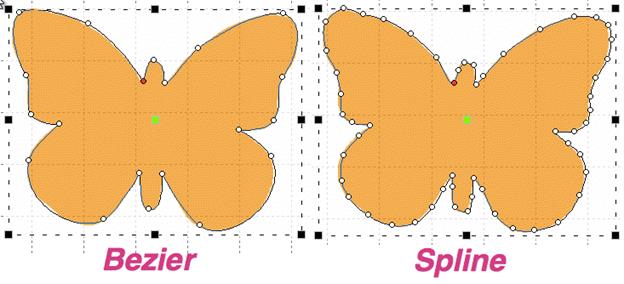
 When
creating and editing outlines for shapes, you are always creating a Bezier form.
For beginners who are inexperienced with Bezier there exists an option to work
without “handles,” both when inputting a shape and when editing a shape. When
the Bezier handles are hidden on an object, you can edit the outline by moving,
adding and deleting nodes. This type of outline is known as a ‘spline’. The
limitation is that you cannot change the shape of the curve between outline
points. That is where the normal Bezier handles come in. You can switch any
object at any time between spline and Bezier, just be aware that when you go to
spline, your edits between nodes will be lost. Generally, we always recommend
that you learn the Bezier and we have made every attempt to ease you into
that.
When
creating and editing outlines for shapes, you are always creating a Bezier form.
For beginners who are inexperienced with Bezier there exists an option to work
without “handles,” both when inputting a shape and when editing a shape. When
the Bezier handles are hidden on an object, you can edit the outline by moving,
adding and deleting nodes. This type of outline is known as a ‘spline’. The
limitation is that you cannot change the shape of the curve between outline
points. That is where the normal Bezier handles come in. You can switch any
object at any time between spline and Bezier, just be aware that when you go to
spline, your edits between nodes will be lost. Generally, we always recommend
that you learn the Bezier and we have made every attempt to ease you into
that.
Note: If you want to quickly
reshape a Bezier curve but don’t understand the handles, we have added a feature
that lets you drag on the outline, between two nodes, and the outline will
follow your mouse, adjusting the handles automatically. This is also very handy
when you want to quickly draw with a very minimum of nodes, (very good for
re-sizing later).
‘Nodes’ and ‘Knots’ mean the same thing as used here, and that
is they refer to the outline points that are drawn and selectable.
Some things you can do with nodes on an outline:
• Select
a node by clicking on it.
• Edit
nodes by dragging them around.
• Add
nodes by double-clicking where you want one to appear, and you can double-click
a node to remove it.
• Drag
around a set of nodes, in which case you will select all the ones in your
“lasso”.
•
Right-click while nodes are selected and change properties and do other
things with the outline.
 When a shape is
drawn, it goes from one node to another. It can either form a straight line to
the next node, or it can form a curve going ‘through’ that next node on its way
to the one that follows. The advantage of curves is that when you scale the
design up in size, the result is a nice smooth outline. If you draw with all
‘lines’, as many have done in the past, you are severely restricting the useful
size of the outline you are creating. For this reason, we normally draw with
curves, and you can switch to a line as you enter points (for example by holding
the ‘ctrl’ key) or you can do it after the design is created.
When a shape is
drawn, it goes from one node to another. It can either form a straight line to
the next node, or it can form a curve going ‘through’ that next node on its way
to the one that follows. The advantage of curves is that when you scale the
design up in size, the result is a nice smooth outline. If you draw with all
‘lines’, as many have done in the past, you are severely restricting the useful
size of the outline you are creating. For this reason, we normally draw with
curves, and you can switch to a line as you enter points (for example by holding
the ‘ctrl’ key) or you can do it after the design is created.
If you think about it, straight lines are not ‘natural’ except
in math; only people create things in the real world with perfectly straight
lines. So, curves and cusps are very useful, unless of course you are making a
geometric design.
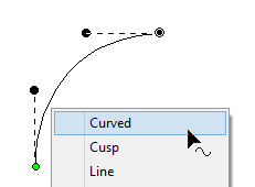
Notes: ‘Curved’ and ‘Line’
node types refer to the path coming toward the node. The path leaving the node
is controlled by the following node.
A ‘Cusp’ allows two
curves to go in different directions away from a common node, whereas a ‘Curved’
node creates a smooth line through the node, transitioning between the two
curves smoothly.
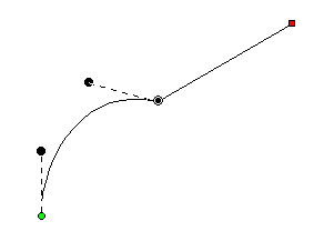
Here is an
example of a curved node in the middle, and a hard point at the end. See how the
path is a flat line going toward the final point. The path shape is defined by
the node it is going toward.
A straight line does not have handles. There is no need, as
there is nothing to adjust. If you want to make it curve, change the node
type.
On any path, there is a green node that indicates the start,
and a red node that indicates the end of the path. A closed shape will naturally
have the end positioned over the start, so it appears red.
If there are only two nodes in a path, you have a section. The
section can be a line or a curve, depending on the later node type. If you add a
third node at the end, and that one is also a curve, now you have a choice as to
what to do with the curve as it passes through the middle node. It can be
smooth-flowing, in which case the curve looks like one continuous line. Or, it
can be disjointed, making two distinct curves, in which case it is called a
‘Cusp’.
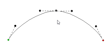
This image shows a selected curved node in the middle of a
3-node path; its handles coming in and going out indicate the travel of the
stitches. The handle coming in is in a line with the handle going out, thus the
curve is quite smooth at the node – it is almost like the node is not there,
other than to direct the path.
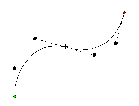
Remember, smooth curves are created by at least three nodes:
an initial starting node, a middle node that the curve runs through, and an
ending node. You can click a long smooth curve that runs though as many nodes in
the middle as you want, but naturally there’s always a start and an
end.
The alternative to a smooth curve is to have a node that comes
‘in’ from one direction, but leaves in another. This is a ‘cusp.’ Cusps are
important, as they make the hard turns where curvy bits intersect – such as the
top of a heart or in shapes of leaves, or almost anything in nature.
 A cusp allows
you to have two curves come together on either side of a point. For instance,
the apex in the top, center of a heart-shape is a cusp. Traditionally digitizers
would make a curve that falls just short of the cusp and then make a line to the
cusp, and then they would begin a new curve going off to the other side. This
has the negative effect of that hard line being visible, especially when scaled.
It also produces a needle penetration where it isn’t needed. We’ll discuss more
on this later.
A cusp allows
you to have two curves come together on either side of a point. For instance,
the apex in the top, center of a heart-shape is a cusp. Traditionally digitizers
would make a curve that falls just short of the cusp and then make a line to the
cusp, and then they would begin a new curve going off to the other side. This
has the negative effect of that hard line being visible, especially when scaled.
It also produces a needle penetration where it isn’t needed. We’ll discuss more
on this later.
Use nodes where the path switches from turning left-to-right
or vice versa. And then when turning, place a node at the ‘widest’ point in the
turn if you need an additional node. This will yield the fewest number of nodes
needed to make the shape. Remember you can add nodes later, or adjust the
curves, if you need to refine the shape.
It is good to use minimal nodes to complete your shape, and
then go back and edit the curves to get the shape you want. The result will be a
nicer object shape and better embroidery. It takes practice, but you’ll find
that you can quickly analyze a shape and create it in very few clicks, and then
the edits required will be much easier.
Normally in graphics a “Closed” shape or outline means that
its start and its end meet up visibly. A shape that is closed can contain
stitches within, and can also have “holes.”
 When
drawing a shape for embroidery, you may wish to have the end-point meet up with
the start-point without calling the shape “Closed.” For this purpose, there is a
button on the tool pane that lets you specify that a shape is closed or not.
Only closed shapes can contain holes.
When
drawing a shape for embroidery, you may wish to have the end-point meet up with
the start-point without calling the shape “Closed.” For this purpose, there is a
button on the tool pane that lets you specify that a shape is closed or not.
Only closed shapes can contain holes.
You can open an outline by clicking the ‘Close/Open Outline’
button up. You will not see a change in the shape, but you can now move the head
and tail nodes away from each other. The tail node will be red.
If you have a node selected when you open the outline, that
node becomes the new head/tail of the outline.
Oftentimes a drawing needs to be perfectly symmetrical. In
this case the first side of the drawing can be made, and the completion can be
done automatically using the menu Create>Outlines>Complete Symmetric.
Left: First half
drawn, Right: After Complete Symmetric
Point Input
The Point Input method is the most commonly used method, and
for most people, it is the easiest. Click the Point button in the Tool Pane and
then start clicking along the line you wish to make.
 As you
create your shape, you can create curved nodes with a normal left-click, line
nodes are made by holding the ‘Ctrl’ key during a left click, and cusps are made
by holding the ‘Shift’ key down during a left click.
As you
create your shape, you can create curved nodes with a normal left-click, line
nodes are made by holding the ‘Ctrl’ key during a left click, and cusps are made
by holding the ‘Shift’ key down during a left click.
You can use the ‘backspace’ or ‘Delete’ to remove points you
have entered. You can cancel the drawing using the ‘Esc’ or ‘Escape’ key.
When you have completed your shape, you can end it by
right-clicking. If you wish to end the shape and also close the outline at the
same time, hold the ‘ctrl’ key while right clicking.
While entering points along the outline, you do not need to
worry about the Bezier handles – they are created for you using some
‘reasonable’ values. Once you have created your shape, if you want to adjust the
handles, you can. Or you can ignore them entirely if you prefer. We’ll talk
about that shortly, in the ‘Editing Outlines’ section, subtitled “Working as
Spline/Bezier”
 This
sounds like the most fun input method, and it is, but it is far from accurate.
The freehand input lets you doodle. You hold the mouse down and drag around.
Where you went gets smoothed out and turned into a curving path. You can click
for a line to a point, and then drag along some more. You can drag and release
any number of times to create lengthy and intricate paths if you wish.
This
sounds like the most fun input method, and it is, but it is far from accurate.
The freehand input lets you doodle. You hold the mouse down and drag around.
Where you went gets smoothed out and turned into a curving path. You can click
for a line to a point, and then drag along some more. You can drag and release
any number of times to create lengthy and intricate paths if you wish.
This is useful in practicality only with the Run stitch type.
Drawing freehand on a computer requires practice, and the more fluid your input
is, the better the result will be. Do expect to spend some time cleaning up your
handwriting!
As with other input methods, right-click to end your
input. Holding the ‘Ctrl’ key when right-clicking will close the
shape.
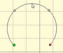
Arc Input
 When you
want to create a curve that is perfectly circular, the Arc input can help. This
input uses three points, clicked with the mouse, to create the arc. The first
and second inputs should be on the arc that you want to create. After the second
click, moving the mouse will draw a circular arc between those first two points,
running through your mouse cursor. Once you have the desired arc, click the
mouse a third time, which ends the arc input.
When you
want to create a curve that is perfectly circular, the Arc input can help. This
input uses three points, clicked with the mouse, to create the arc. The first
and second inputs should be on the arc that you want to create. After the second
click, moving the mouse will draw a circular arc between those first two points,
running through your mouse cursor. Once you have the desired arc, click the
mouse a third time, which ends the arc input.
This program, like most drawing programs, allows Bezier forms
to take up to 90 degrees per node. If the circular arc you create goes around
more than a quarter of a circle, multiple nodes will be added.
You can edit the nodes which the arc input creates as you
would any other.
Shapes Input
 The Shape
button activates a mode that creates a shape by dragging the mouse on the design
page. The down-pointing arrow next to the image on the button makes the shape
selection panel appear.
The Shape
button activates a mode that creates a shape by dragging the mouse on the design
page. The down-pointing arrow next to the image on the button makes the shape
selection panel appear.
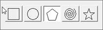
To change the shape, click on a button to select the shape
that the tool will create.
Click the shape button, and then drag on the design page. The
size and orientation (rotation) of the shape is controlled by the length and
direction of your drag. Let go of the mouse button and the shape will appear on
the page as a new object.
Shapes that might be useful in rectangular proportion, such as
rectangles and polygons, will follow the drag from the top, left diagonal corner
to the bottom, right corner. If you wish to make things perfectly square, hold
the Shift key down while dragging.
Some shapes have properties to adjust details of the shape,
such as corner roundness, number of corners, density of a spiral, etc.
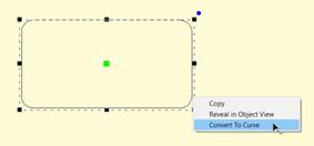
Shapes, as objects, have these special properties for the life
of the shape and can be adjusted at any time. The shape’s outline can be edited
by converting the shape to an outline. Right-click on a selected shape and
choose ‘Convert to Curve.’
Whether it is used as a shape or converted to a curve, the
object can have stitches applied.
 The
professional graphics industry has adopted this method of input and it takes
getting used to. Select the Bezier Input method using the button on the Tool
Pane. To begin, click and drag. This will create an initial Node and a Bezier
handle. The next time you click and drag, you will be creating the points needed
to complete a Bezier curve section, and also begin the next one.
The
professional graphics industry has adopted this method of input and it takes
getting used to. Select the Bezier Input method using the button on the Tool
Pane. To begin, click and drag. This will create an initial Node and a Bezier
handle. The next time you click and drag, you will be creating the points needed
to complete a Bezier curve section, and also begin the next one.
If you simply click, you will create a flat curve – a line.
To create a cusp, hold the ‘ctrl’ key down when you click and
drag.
Right-click to end your input. Holding the ‘Ctrl’ key
when right-clicking will close the shape.
We have made the editing of outlines work in two modes, Bezier
and Spline. To understand spline, imagine something flexible, but with a little
bit of spring to it – in the original context a spline was a light piece of wood
that could be shaped around things. In this use, it is a line that flexes around
‘Nodes’ on the screen (where you have clicked). The more clicks you give, the
tighter the spline will have to bend in order to conform to the shape you
want.
Bezier lets you adjust the curves using handles, as we have
discussed. Now you get to decide how you will perform your edits.
The
Spline/Bezier button on the Tool Pane will toggle all the selected objects to
either show their handles, or hide them. Remember, if you switch handles off,
the outline will change to its automatic shape, and you may have to add some
nodes in order to recover the curves. Spline mode will almost always require
more nodes than Bezier.
If no objects are selected, this button also sets how your
next objects will be treated, once drawn. This button also acts as a program
preference, so if you choose to always work with Bezier, the next time you run
the program this will determine the state in which you start.
You can select a node by clicking on it. You can use the Ctrl
key while clicking to select multiple nodes. If a selected node is clicked with
the Ctrl key it will be de-selected, as is typical with virtually all computer
systems.
You can also select nodes by dragging around them. First,
select the object that you would like to edit. Then drag around the nodes you
want. When you release your mouse button, the nodes inside the area you dragged
will be selected.
You can also operate on holes, carving lines and breaklines in
this manner – drag around the nodes you wish to adjust.
Double click on the outline to insert a node. Double click on
a node to remove it. If you have a node or nodes selected, you can also use the
‘Delete’ key to remove them.
You can switch the type of any selected nodes by
right-clicking, which will bring up a pop-up menu. The node types are Curve,
Line and Cusp, as we have discussed. Remember that a curve will allow stitches
to pass through it without forcing the needle to stop at the node, but by
necessity of the shape, lines and cusps will cause the needle to land on those
nodes.
Sometimes an inclination line will be made very near a node.
If that node is moved so that the inclination line is left in empty space, the
incline will be removed automatically. We suggest you adjust your outlines
first, then go back and add and adjust your inclination lines.
Spline mode has the ability to insert and remove nodes to
adjust the shape. If the curve is too far away from the outline you want, simply
add more points on the outline where the shape you have is ‘most different’ or
furthest away from the artwork.
It is often best to begin with minimal nodes in the outline,
only basically representing the shape you are drawing. Then, go back and insert
only the nodes that are needed to pull the outline into shape. Doing it this
way, you will use a minimum of nodes.
Why use a minimum of nodes? The stitches being generated have
to look at all the nodes on your shape. If you insert hard nodes or cusps, the
needle will penetrate at those nodes, so you get less desirable embroidery and
an increased stitch count. Another reason to use minimal nodes is for editing
purposes. Suppose you test sew your design and realize you need move overlap for
registration issues – the fewer nodes, the easier and faster the edits can be
accomplished.
Editing paths with Bezier handles exposed is not hard, and is
very intuitive once you get past the first few minutes or so.
Editing is accomplished by dragging the handles, which adjusts
the curve as you drag. You can also drag the outline itself into place, which
will adjust the handles for you. When dragging the outline, the closer you are
to a node, the more that node’s handle will be adjusted, rather than the one you
are farther away from. Because this can make your handles go ‘wild’ we do not
let the outline drag if you grabbed it within 5% of the ends of the outline in
either direction. It is best to grab the curve somewhere in the middle and drag
it, then adjust the handles to perfect the shape.
Note:
Sometimes art will have the
handles ‘hidden’ under the nodes. Drag the outline and the handles will move,
exposing them so you can drag them around as needed.
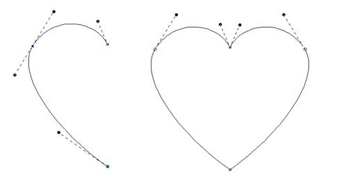
Here’s a step-by-step example of making use of minimal nodes
while drawing, and good use of re-shaping: Make a heart, starting at the bottom,
using all Cusps (Shift key). You only need four points! Ctrl-right-click to
close the outline:
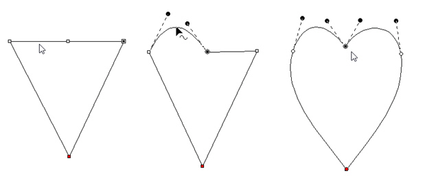
Next, hover your mouse over the curve in between the top left
two points as shown, and drag the curve up. You will see the shape beginning to
appear. Repeat the drag for the other side. In the example above, we’ve made the
sides smooth too. Do any editing desired for the overall image, and you have a
low-node-count shape that looks great!
There are also some tricks that we would like to share.
Trick 1: A favorite old movie of ours, Ghostbusters has
the line, “Don’t cross the streams!” In the movie, it implied that ‘Bad Things’
could happen. What we’re saying here is, “Don’t cross the handles.” It’s not
that you cannot cross the handles – you can – but certain object types will not
understand what it is you’ve done. So, we discourage it.
Trick 2: Another thing to consider is that the handles should
generally be in the direction of the travel of the path. If you have your
handles pointing away from the travel of the stitches, then the stitches may do
a “Two-Step” which you might not want to happen.
Trick 3: Sometimes you will inadvertently wind up with a
handle hidden under the node it is attached to: it is a handle with no length.
You can recover these by mousing-down in the middle of the curve and dragging
the outline, which reorients the handles for the curve you are dragging. Once
the handles are exposed, you can position them as needed.
Trick 4: Use nodes where the path switches from turning
left-to-right or vice versa. And then when turning, place a node at the ‘widest’
point in the turn if you need an additional node. If you have extras, you can
delete those and adjust as desired.
When you have two or more lines that should be connected, use
the menu Create->Outline->Connect to make them into a single line. While
you are drawing, it can happen that you end the drawing before the outline is
fully created. You can simply create the rest of the line as a separate object,
then select both and connect them.
When connecting lines, the head and tail of the first line in
the sequence are preserved, and thereafter the lines that are being connected to
it will be reversed as needed to ensure the nearest connecting point. You do not
need to have your line endpoints adjacent, as a connecting line will be added
for you if needed.
When you create a line, there is a point where you started and
a point where you ended. If you wish to reverse the direction of points on the
line, use the menu Create->Outline->Reverse Points.
Generally, the outline order is not very important for the
creation of stitches. You may, however, want to use this when working on
connecting shapes you have made.
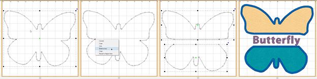
You can select two points across a closed outline and break
the outline into two using the context menu option ‘Break across’. This is
sometimes useful in logo or promotional designs, where you have original shapes,
but want to separate them and insert a word or other design element in
between.
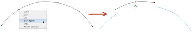
If you have an open shape selected, with one or more nodes in
it selected, the context menu option, ‘Break at point’ will split the object
into multiple objects.
The menu Create > Outlines has Reconstruct Outlines to take
vector shapes and try to recreate them with fewer points. If you’ve brought in
something traced from a bitmap, it may have vector nodes every mm or so, making
an impossibly ugly outline. Copy and paste a new one directly over the original.
Sometimes it is useful to lock the original so as to avoid
selecting/moving/editing it by accident.
Reconstruct Outlines on the copy. This will reduce many nodes,
but they’ll probably not be exactly what you want. You can now edit, and even
reconstruct again, to get a clean vector shape. Use the original that you’ve
locked in place as a reference shape. Once your new shape is clean, delete the
original.
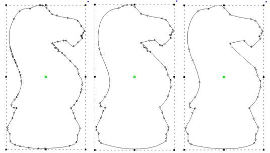
Left: original,
Middle: After Reconstruct, Right: With minor edits
Holes
 Holes or
‘voids’ can be added to artwork for stitch types that use them such as
Fills.
Holes or
‘voids’ can be added to artwork for stitch types that use them such as
Fills.
In order to be able to add a hole to a shape it must not only
appear closed, but actually be closed. You can tell by looking at the ‘Close
outline’ button on the Tool Pane when the object is selected. If the button
appears depressed, the shape is closed. If not, you can click the button to
close the shape.
Not all stitch types allow holes. When it is allowed, the ‘Add
Hole’ button on the Tool Pane will be enabled. You can push this button and then
begin drawing the hole. Right click to complete your drawing as with any drawing
operation. To add another one, simply click the button again. There are no
limits to the number of voided areas (holes) that can be on a shape.
The hotkey for adding a hole to the currently selected object
is ‘o’.
If you have drawn several objects, or used path operations to
create them and you want to combine holes from multiple objects, select all the
objects and use the menu Create->Outline ->Combine Holes.
Holes can be removed by selecting a node on the hole and using
the right-click pop-up menu entry, “Delete Hole.” To remove all holes from an
object at once use the menu ‘Create->Delete Holes’.
Similarly, you can separate the hole into a new object, as an
outline, with the right-click pop-up menu entry, “Separate Hole.”
If you have multiple objects with original art that has holes,
but you would like to separate them out as individual objects, use the menu
Create->Outline->Separate Holes.
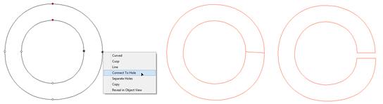
Connect to Hole
Sometimes you’ll need to turn a shape with a hole into a
continuous outline, such as to make a satin stitch. To accomplish this, select
two near points, one on the outline and one on the hole. Then use the context
item, ‘Connect to hole.’ The hole is now part of the outline, as shown:
Delete Holes (Level 2)
The menu Create > Outlines has a convenience command to
remove all the holes from an object in one step.
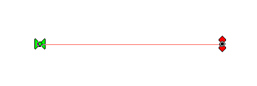
While not directly used in defining a shape itself, there are
Entry and Exit points that accompany outlines once a stitch object type has been
assigned.
These Entry and Exit points indicate the preferred location of
the beginning and ending of the stitching process. In the illustration, the
stitching would begin at the green handle on the left, and finish up at the red
handle on the right. You can drag the handles around anywhere on the outline.
You cannot drag them to a hole, if the shape has one.
There are some object types where the stitching follows an
algorithm that comes back to a single point. Those object types are noted in
their respective sections. Entry and exit points are used to limit the
number of jump stitches in a design. By having the objects end and begin at
near-most points, the transition stitch between the objects is minimized.
The Entry point on an object is where the stitching will
begin, and Exit is where the stitching will complete. The purpose of adjusting
the entry and exit is to minimize (or eliminate) traveling runs needed to move
from one object to the next. This also lowers the stitch count.
Note: Usually you will want to set
the Entry and Exit points after you have sequenced your objects.
Most stitch generation has the availability of adjustable
Entry and Exit points, although some only use the Exit such as Stippling, where
stitching is continuous.
Entry and Exit adjustments are usually not noticeable in the
resulting stitches except for Runs. Runs by definition have styles such as
Single, Double, Bean, etc. When you have a single run enter and exit at the same
point, you are going to have a double-run result. The exit handle forces the
stitches to run to the exit, over top of what’s been stitched. This can be handy
when creating redwork or running-stitch designs as you may set the Exit Handle
as needed, and not worry about changing the property to a double.
Entry and Exit on a stitch object are controlled by the green
(Entry) and red (Exit) handles on the outline of the object. Drag the handles to
the point on the outline as desired. Generation of stitches is
automatic.
Use the menu Create->Auto Entry/Exit to set the Entry and
Exit handles on selected objects. The ‘Automatic’ process looks for the nearest
points on the objects if they don’t touch, or to a point where they touch, if
they do.
 The Magic
Wand is a tool used to create outlines from bitmap images. There are two styles
– a wand for filled areas, and a wand for lines. The Line Wand tool is available
in Level 3.
The Magic
Wand is a tool used to create outlines from bitmap images. There are two styles
– a wand for filled areas, and a wand for lines. The Line Wand tool is available
in Level 3.
When you turn on the Magic Wand, you can click on the backdrop
image and the Wand will look at the color where you clicked, find all pixels
(dots) around it with a similar color, and then make an outline out of all of
those similarly-colored pixels. The shape that a Magic Wand creates will not be
as clean as one drawn by hand, but they are fully editable, and can be an
effective way to get started on some simple projects.
Note: When you like the wand
result, right-click to end the wand to keep what you’ve made. If you click the
Wand button again, or hit the ‘Esc’ key, you cancel the
operation.
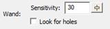
Because images differ in quality, when you click on the wand,
the Sensitivity controls will appear. A low number of sensitivity means the
pixels it is looking for will be very similar to the one on which you clicked.
If you have an image with a mottled texture, for instance a piece of scanned
fabric in the picture, you can make the sensitivity large, for example use 150,
and the outline will be expanded to include more pixels to get a better
outline.
As you adjust the sensitivity the wand will re-wand where you
clicked automatically. You do not need to click again.
Important: When you like the wand
result, right-click to end the wand and keep what you’ve made.
The wands will create as many objects or holes as you like.
Once your sensitivity has been adjusted and you have an outline you like, simply
click the wand again in another area to begin making a new object. Right-click
to end object creation once all objects have been wanded.
Expand the Object View to watch the objects get created –
sometimes a higher sensitivity will result in fewer objects or outline nodes,
which is desirable. Other times, higher sensitivity can add ‘noise’ in the edge,
or even fail to find a shape at all when the outline and background are
similar.
The first wand button creates an outline around areas filled
with a consistent color.
You can also use the wand during an ‘Add Hole’ operation.
Normal graphic fills, such as those from a cartoon image will
not need a high sensitivity to the color used. You can reasonably use the
default number. If the image is scanned from a print, you might need to increase
the sensitivity a little. Try different levels to see what you get. Note that
some large images with a high value for sensitivity can take longer to
wand.
The second magic wand (Line Wand) is for line art drawings and
line art areas in a cartoon-style image. The color you click on has all of its
pixels gathered and thinned to make a running-stitch object. The line drawing
may be very complex, and the Line Wand will create as many objects as it needs
to to stitch around the entire design doubly. This is useful for automatic
outline or redwork designs. The wand will set all the Entry and Exits and create
a double-run design ready to sew.
The objects that are created also have Styles used. You can
adjust these styles, thus adjusting the style of the result. Please refer to the
Styles section for details.

To further explain; let’s examine a simple ‘T’ shape that
might represent any ordinary outline drawing. The wand will find a starting
point, run to the ‘T’. Now it must go both directions in order to sew the entire
shape. To do this, it will run out on one side first. Then run back. This
process repeats for the second side. Now that this part of the path is complete,
it can return to where it started. In this way, the entire design has been
stitched over twice.
If you don’t want the entire design branched in this fashion,
the objects created are editable – you can do what you like. Also, the objects
have “Line Art” styles named for what they are doing within the path. By
changing objects labeled ‘Forward’ you are changing the run out – not anything
with topstitches. Change the ‘Double’ for branches that are open-ended – they
run out and back. Change the ‘Return’ for topstitching as the stitching comes
back over itself.
Line-Wanding Grayscale Images
Some bitmap images will be like an old black-and-white
television image, and we call that grayscale. When you load a grayscale image,
the chances are good that the image will have lines that look nice and clean,
but are really all sorts of gray variations, like a pencil drawing. Grayscale
images are fine to work over, but if you plan to use a magic wand line input you
may want to save the image as a Black and White (1-bit) image, if you have an
image-editing program such as Paint.
Basic cut/copy/paste operations are supported, and there are
some additions you’ll want to know about especially for sequencing the design,
as we’ll discuss shortly.
When you cut, you are removing items from the design page.
Pasting them puts them back, and keeps a copy in memory so you can paste
multiple times, even on multiple design pages.
As we have discussed, there are Designs, and there are
Objects. Designs contain objects, so when you cut, copy or paste a design, you
are doing it to an entire design including all the objects within it. Pasting a
design will place it at the end of the sequence on the design page (visually at
the bottom of the Object View list.)
Pasting objects will place them at the bottom of the last
design in the sequence, unless you immediately precede the paste with a
menu->Create->Design->Set Current Design.
When you cut or copy something for a paste, its location on
the design page is stored with it. When you paste, either on the same page or
another, that location is used for the paste – it will paste in the same place.
However, if you have a new location in view, say you are zoomed to a new area of
work, and the original location is not visible, the center of the current view
is where the paste will occur. This helps minimize the amount of moving-around
of pasted items you will need to perform. Simply zoom in comfortably to the
location where you would like the items pasted, and Paste (or
‘Ctrl-v’).
You can decide where to paste objects by selecting a ‘target’
object, and then right-clicking on it in the Main View. You will have the option
to ‘Paste Under’, ‘Paste Over’ or ‘Paste Replace’.
Pasting Under will paste the cut/copied items before the first
selected item in the sequence (the pasted items will sew first). Pasting After
will add them after the last selected item in the sequence.
Paste replace is a special feature. If you have a design
element that’s being used repeatedly, you may have pasted it into multiple
places. But what happens if you later discover that you need to edit that
element? Perhaps the stitching needed to be changed, or a connective run was
missing from the original. You can fix this by copying the revised element, then
selecting an item it is to replace, and Paste Replace will remove the item
selected and replace it with the copied one. It will be centered where the
original was, and it will be in the sequence in the same place as the original
item.
This is also useful for placeholders while you are creating.
Suppose you know you’ll need a flower, “Here, there and there.” You can simply
insert an object to mark the locations of those, and Paste Replace them
later.
An especially useful feature to help with this is ‘Grouping.’
If the element contains multiple objects, group them using the Edit menu or
‘Ctrl-G’. When pasting the first time, paste the grouped objects. Later, when
you perform a ‘Paste Replace’, you will first select the destination group by
clicking on it in the Main View and perform the ‘Paste Replace.’ This selects
the entire group and will remove that entire group when you Paste
Replace.
Objects can be grouped so that when you select one in the Main
View, all will be selected together for operations such as Move, Rotate, Mirror,
Cut/Copy/Paste, etc.
Use the Edit menu->Group or ‘Ctrl-g’ for this.
Note: When items are grouped, they
are still individually selectable in the Object View, and can be edited singly
if selected.
If you have
a design selected when grouping is performed, the design is part of the group.
This means sequencing and copy/paste operations will be done at the design
level. If you want all the objects from a design, but not the design itself,
make sure to check the Object View to see that the design is not
selected.
The Edit
menu->Ungroup (Ctrl-u) can be used to ungroup objects.
You can
group selections that contain sub-groups. Ungrouping will not ungroup the
sub-groups – those will have to be ungrouped with a separate ungroup
command.
The sewing order of the design is very important. You don’t
want your design to sew randomly all over the fabric. It will leave jumps, or
have increased trims, or worse, increased color changes, and if you sell
designs, your customers won’t be happy.
There are ‘best practices’ for sequencing on different
embroidered goods, most notably hats. If you’re creating a design for a hat,
you’ll want to attempt to sew from the center outward. This helps keep the
fabric in place and flat in the hat frame.
For regular designs, it can often be useful to have stitching
work the edges of the design first, in effect anchoring the stabilizer, then
work from the center out.
Think about how you would like the design to sew. You’ve
probably watched hundreds of designs stitching out, and you can use that
experience to help you decide what to sew in what order. Things that connect are
pretty easy to figure out – you want them to sew without jump stitches, usually.
If you are new to embroidery, we recommend you spend some time embroidering so
you can get used to the stitching process. If you can look at a complete design,
figure out what object types were used to make it, and predict which objects
will sew in what order, then you are ready to take on sequencing.
Work on the sequence on a per color basis. There is always a
trim when the machine goes to the next color, so imagine your machine working
one color at a time. And yes, there are times when it is necessary and even a
good idea to revisit a color – you don’t have to put all your colored objects
together. Layering and Shading are good reasons to separate a color into
sections with different colors in between.
Once you have a sequence in your mind, you’ll need to adjust
the objects to match. And for that, you’ll need to know how to change the
sequence your design.
The Object View shows you the sequence of your objects in the
design. You may have a lot of objects for a complex design, and that’s normal.
If the design can be broken down into separate designs themselves it may be
helpful. For instance, if you have a picture of a flower and a butterfly, you
might make them separate designs on the page, and create them separately.
When you right-click on an object in the Object View, you get
a pop-up menu that lets you move designs in the sequence. This is often handy
for simple or small moves.
You can also select objects in the Object view and drag them
to new positions in the sequence. The items being moved will go into position
immediately after the item you release the drag upon.
Remember that designs operate at the root level of the
Object View. If you move a design into the middle of another design, you will
get three designs – the first, up to the point where you pasted, the one you
pasted, and then finally the rest of whatever the first design contained.
If you have a Design selected, and not just objects, the
Design itself will move. If you wish to move objects only, make sure you do not
have the Design selected.
You can drag all the items out of a design, leaving an empty
design. If this happens, you can select the design in the Object View and delete
it using the Delete key or the Edit menu ‘Delete’.
When items are locked or hidden, they are always still
selectable in the Object View, so be aware of inadvertently selecting locked
objects.
A simple and effective method of sequencing is Cut and Paste.
You can Cut any selected objects and Paste them at the end of the sequence, or
before or after any other object.
The normal Paste (Ctrl-v key) will paste the objects at the
end of the design.
Using this method, you could drag or click-select objects,
cut, paste, and move on. You are sequencing the design by the order of your
cut/paste operation.
Sometimes you have made a design, perhaps with a lot of
copy/paste operations, and you wind up with objects of different colors out of
sequence. You may want to sequence them by color before adjusting the sequence
further. To accomplish this quickly, select the objects and use the menu
Create->Auto Seq. by Color.
A fast way to get objects sequenced (although not a perfect
method) is to automatically sequence them. This requires that you first decide
on what you want to sew first, and what you want to sew last in a set of
objects. Manually sequence those two objects so they are the first and last in
that whole set of objects. This gives the program something to use as a starting
point.
Next, select the set of objects, including the first and last.
Use the menu Create->Auto Sequence. To select the set, you could drag around
them in the Main view, or Ctrl-click them in the Main view, or click the first
one in the Object Tree, and shift-click on the last one in the Object view. See
the Object view section of the program help for more ways to select.
The program attempts to minimize the travel among objects so
that connective runs or jumps are shorter or eliminated. This form of sequencing
is not as good as what your brain can do, with a little thought, but it is a
reasonable approximation, and sometimes a helpful starting point for your manual
sequencing process.
Similar to the Cut/Paste sequencing method, you have the
option to perform the same thing with single clicks. The Sequence Mode button on
the Tool Pane begins this mode. Click on an object. That object and anything
grouped with it will be moved to the tail of the design. Click on the next
object and the same thing will happen. Thus, if you click on all the objects,
starting with the one you want to sew first, and ending with the one you want to
sew last, you will have sequenced the entire design.
To exit the mode, click the button again or use the ‘Escape’
key.
You do not need to sequence the entire design – you can
sequence the parts you want. Then if needed, select what you have sequenced, cut
the objects, select a target object and perform a ‘Paste Before’ or ‘Paste
After.’
Sequence by Assigning Stitches
If you have imported artwork as a vector file, that artwork is
flagged by the program as ‘newly imported art’. With this art, the program
assumes the sequence is not designed to sew.
As you assign stitches to objects, the program will begin
sequencing the objects to the end of the design. The purpose of this is to allow
you to perform both jobs simultaneously; assigning stitches and creating the
sequence that the objects will be sewn.
If you do not want this to happen on the imported file’s
objects, simply select it in its entirety and click ‘Line’. This has the effect
of clearing the ‘newly imported’ state.
Ties are stitches that form knots in the embroidery both
allowing for trims and to pull up the bobbin thread when stitching has just
begun. We refer to these as entry ties and exit ties, but some may call describe
it as “tying in” and “tying out.”
In each object property page, you are given the opportunity to
explicitly set ties. Click the button with the bow tie icon on it.
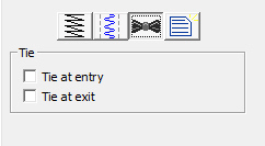
The ties are computed automatically to use the direction of
stitching to find an innocuous angle, then stroke a few stitches forward and
back – enough to bind the stitch and bring up the bobbin thread. For most items,
even if a tie-in misses a stitch in the case of a stubborn bobbin thread, the
underlay will have enough stitches to spare.
You can of course add a few manual stitches, if you choose,
with a separate object, but generally the automatic ones work.
Transits are what happen when the embroidery moves from place
to place – often between objects. Rather than adding transit properties to each
object, the overall design page has transits set in the Program Preferences on
the Files tab. When performing commercial embroidery, small movements between
objects can have a tightly nested run, which buries the stitches, and no trims
are desired because they slow down the process. For home and hobby embroiderers
the tie/trim/tie approach seems to be universally approved. To accommodate these
differing viewpoints, the preferences “Run when jumps are small” and “Ensure
ties surrounding jumps” allow for automatic negotiation of the transits.
“Run when jumps are small” allows for two nested 1.5mm
stitches – or a total 4.5 mm between objects before the transit will allow a
single whole stitch.
When the stitch exceeds this value, and “Ensure ties
surrounding jumps” is set, ties are ensured in both directions, and a trim
command is sent out. Some machines have lower limits to the length of a movement
before they will trim, often 5mm, but in case the user wants to hand-trim the
design, the ties are there to prevent the embroidery from unraveling.
A difference in style: Most hobby
embroiderers will trim everywhere they can. However, commercial embroiderers
wouldn’t nest the runs if the result was something they got complaints about –
they don’t. Only an embroiderer with an eye for it would notice a few nested
stitches, usually between lettering. So, you might just want to save yourself
some effort, and turn the transit options on.
Styles allow for repeated use of properties on a given type of
object. There is a QuickStyle button on the top, right of each object property
page. When an object has been assigned a style, that style will be highlighted
in the style list, shown on the Style properties for the object. If an object
was given a style, but then modified from that style, its style name will have
an asterisk (*) following the style name.
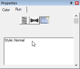
When you begin creating objects having just run the program,
the default styles are being used, called “Normal.” These have been tested to be
reasonable for all-around conditions, but naturally properties exist for a
myriad of reasons.
If you click on the ‘Normal’ style it will reset the object(s)
to that style. Keep in mind that all properties will be reset.
 A line is
simply a shape. It has no stitches applied to it. When you bring in vector
files, or TrueType they are lines. As artwork without stitches, they have no
properties other than color.
A line is
simply a shape. It has no stitches applied to it. When you bring in vector
files, or TrueType they are lines. As artwork without stitches, they have no
properties other than color.
 Manual
stitches are straight lines, with the needle dropping at every node. Manual
objects are typically used in the creation of Motifs, but occasionally you may
need a manual stitch for a tie or something really small, where runs will not
calculate well – for example when adding a single stitch to cross a satin column
when creating a Celtic knot as previously described.
Manual
stitches are straight lines, with the needle dropping at every node. Manual
objects are typically used in the creation of Motifs, but occasionally you may
need a manual stitch for a tie or something really small, where runs will not
calculate well – for example when adding a single stitch to cross a satin column
when creating a Celtic knot as previously described.
To protect the user from resizing the design and obtaining a
very large stitch, manual stitches have a property that limits the maximum
length of an individual stitch.
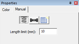
 Run
stitches are the heart of any design. You could, with patience, create virtually
any design with run stitches. There are a lot of variations to them as well.
Run
stitches are the heart of any design. You could, with patience, create virtually
any design with run stitches. There are a lot of variations to them as well.
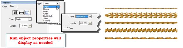
A basic single run is how your stitches travel from one point
to another. The run has a length for each step. With curves, however, the stitch
length may shorten when needed to go around a tight turn. This is described as
“chord gapping” in math parlance. It creates a run that is more faithful to the
shape.
When runs encounter curved nodes on the path they are
following, they do not need to cause a needle penetration, but with cusps and
straight lines, they do, otherwise the stitches would not match the outline. So,
if you see a needle penetration that makes the stitches look uneven in length in
your run, go back and check for an inadvertent line or cusp point.
A double run is one that makes its path like a single run, but
then reverses its steps to return to the starting point. For this reason,
when you switch a single run to a double, the Exit point will be reset to match
the starting point for you automatically.
A Bean stitch is like a traditional sewing machine’s
triple-stitch. The needle makes two steps forward, and one back. This provides a
heavier stitch that stands out better against a pile fabric. The bean stitch
also has an option to repeat the stitch (in place) up to 9 times, which can make
a heavy hand-sewn look. If you use this option, we recommend a longer stitch
length so that the fabric/stabilizer can support the tension created by that
many stitches.
The chain stitch is homage to heirloom hand sewing and
forms a pretty effect that looks nice when combined with traditional design,
especially floral.
Like the chain stitch, the Back stitch and Stem stitch are
also traditional heirloom stitches. As you select these stitches, you will see
properties appear for them.
The Sashiko stitch attempts to emulate the Japanese hand
sewing look. The word Sashiko translates to “Little Stabs” and describes the
short interval between stitches. To accomplish the look, this run creates a
small step forward, followed by a multiple-pass stitch that is a little bit
thicker. At arm’s length, the effect is rewarding. Used in the traditional
colors of white thread on indigo fabric, the stitches resemble grains of rice
laid end-to-end.
 Motif runs
use patterns of stitching along a path, much like the decorative stitches of a
sewing machine.
Motif runs
use patterns of stitching along a path, much like the decorative stitches of a
sewing machine.
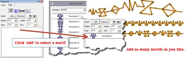
When you initially set an object to a Motif run, it will only
have normal run stitches in it. You will need to add a motif to the run. Click
the ‘Add’ button and the Motif Selection window appears.
Once you have selected a motif, for the run, the run will
re-generate with the motif. The motif will also appear in the list box in the
bottom of the property page. You can add as many motifs as you like, and they
will be added to the sequence in the order that you add them. Each motif has its
own properties that you can adjust. Select the motif in the list to adjust its
properties. You can remove a selected motif with the ‘Remove’ button, next to
‘Add’.
The height, width and rotation of the motif are set as their
name implies. The mirror buttons will flip the motif in the sequence. You might
want to have two copies of a motif ‘facing each other’. This can be done by
adding the motif twice to the list, and then flipping one. The ‘Gap’ of the
motif indicates that some amount of space should precede the motif, after the
previous one.
The Motif Scaling button allows you to incrementally adjust
the size of each motif in the run. This makes for a decorative effect. If you
increase the size, start with the motifs all at a regular or small size in the
Height and Width fields. Then you can add a few percent of size for each pattern
that is displayed. If you want to create your run with motifs decreasing in
size, start with the motifs’ height and width as large as you will want, and
decrease will make each successive pattern smaller. This may take some trial and
error to get the result, but the effort is worth it, especially if you want to
run ‘center-out’ and have motif run scaling in both directions.
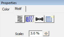
 Making
patches has been common since Roman times, at least. From garment repair to
military insignia to fashion item, the humble patch has been with us and will
continue to be part of our wardrobe culture for the foreseeable future. You may
also have heard of patches called emblems or crests: They’re synonyms.
Making
patches has been common since Roman times, at least. From garment repair to
military insignia to fashion item, the humble patch has been with us and will
continue to be part of our wardrobe culture for the foreseeable future. You may
also have heard of patches called emblems or crests: They’re synonyms.
Standard technique for patch production today is to use an
embroidery machine or sublimation to put the design on the patch, usually made
of twill, then the patch is taken to an overlock machine to have its edges
finished.
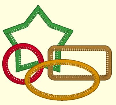
Some common patch shapes
Sometime in the mid-19th century, the Merrow
company, under a couple names, headed by Joseph Merrow, began producing overlock
machines. About the same time, Wilcox and Gibbs also produced similar overlock
machines. Both brands survive today, however, the term merrowing has been used
in the patch production industry for all recent memory. For those curious about
history and the history of textiles, look those companies up as they’ve both got
some great stories in their past.
A merrowed border is a three-thread overlock. Like a serger,
but without having the machine cut as it goes. It gives patch edges their
distinctive look, with the fan-shaped edge rolling over to the back of the
fabric, and the top needle’s apparent chain stitch.
To simulate a merrowed look, some have resorted to using a
motif that resembles the fan-and-chain. It’s okay but lacks the ability to
handle shapes that are complex. Turning corners, especially at odd angles,
requires a lot of manual editing.
This edge stitch creates a faux merrowing look
programmatically. You can use it on virtually any patch shape. Where corners
break sharply, the edge stitch will do what a machine operator would do: It
lifts and resets the overlock. Thus, you will see corners and shapes that very
much look merrowed, but a merrow machine would be unlikely to accomplish.
Note: If
you have a lot of patches to produce, invest in a Merrow machine or similar.
They’re fast and efficient. If you’re doing small batches and prefer to do it
all in the embroidery, this stitch is for you.
The patch objects normally precede the design; you embroider
on the patch. The patch objects consist of a position run, a material run or
fill, and a topstitch that is the merrowed finish. The position run is used to
place a patch on fabric, a project or wherever you need to see it go in your
embroidery hoop. Then you have some choices:
1.)
Patches can be formed on fabric (usually fused twill) and cut after the entire
patch is complete. This involves cutting close to the outside edge of the patch,
then using a heat source (hot knife, wood burner, soldering iron, lighter) to
seal and finish the edge.
2.)
Patches can be precut and laid on a stabilizer in the hoop. This can be a mesh,
fusible, sticky or even wash-away. There are some companies that make pre-cut
patches, or you may choose to use a fabric cutter to cut a custom shape.
3.)
Patches can be created with no cloth using a fill that has enough layers to make
it freestanding. This uses a lot of thread and takes a lot of time, so it is
impractical for production of a large quantity of patches.
4.)
Patches can be sewn on a fabric or precut patch back, then the color and texture
may be enhanced to suit using a light fill across the surface. This fill
typically has about half the density of a normal fill and simply aids the
surface color and texture. It is a technique commonly seen in military
patches.
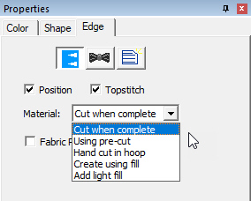
The properties of the Edge
stitch.
The control of the type of patch is done using the material
drop-list. There are also checkboxes to control the inclusion of the position
run, which may not be needed, and topstitch (overlocking) which may be sequenced
into a separate object.
The Fabric Preview option, used when there is no material
fill, is for visualization of color, and functions identical to the same option
in applique objects.
Patch objects usually run before the full design. This allows
proper registration of the border to the position and material levels.
Occasionally there is the need to have the design run after the position, but
before the topstitch. In this case, duplicate the object, and place the copy of
the object after your design sewing. On the later copy, select ‘Cut when
complete’ and deselect the Position. On the earlier object, deselect the
Topstitch option. If the patch has no applique steps, it
can run after the design.
Patches can be made using other films, tear-away or wash-away,
as hooped stabilizer, and the applique method of laying the patch into a
position stitch can be used. This improves edge removal, but requires the
backing removal. If you use this method, split the patch into two objects,
sewing the topstitch after the design, as the needle penetrations will weaken
the stabilizer and perforation can occur which can affect the registration of
the design. Moving the topstitch to sew after the design, the stabilizer has a
better chance of doing its job.
Entry of a patch object defines where the position or material
run will begin. The exit point simply travels from the final stroke of edging to
that exit. It may or not be useful to locate that exit, but it is an option.
Please realize that in order to do what it does, the program must select certain
things to happen in sequence.
Finishing the patches can be done by hand
trimming any excess threads. If you’re using wash-away stabilizer, and the
design has hard corners, try adding a drop of anti-fray to the corner before
washing the stabilizer out. Alternately, finishing with heat will seal off
anything you’ve cut.
When using a poly mesh or twill, always
fuse it. Either heat-fusible material or a really good adhesive stabilizer will
help. When finishing, cut with a hot knife or curved embroidery scissors. Then,
use a heat source and take care to seal the edge, but not melt the patch itself.
It’s easy to get too much heat applied. Use a tool where you can control the
temperature, if you can, otherwise, use a steady hand and don’t get too close
for too long. Woodburning, soldering or hot knife tools are good. A lighter
is a tool, but not as easy to control.
The standard edge width for a patch is 4.2mm or about
3/16th of an inch. When sizing the patch around your design, leave
some whitespace, about the same as the edge width, in order for the design to
look balanced. If you’re using the inflate tool, about 8mm is reasonable.
The patch edge forms at the outline, with a minimum cast over
the outline. This enables you to use predefined shapes, such as the ubiquitous
.svg files that appear on the web these days. Keep this in mind as you plan your
outline – the edge of the stitch is the edge of the patch, and you need 3.6mm of
interior space for the overlock.
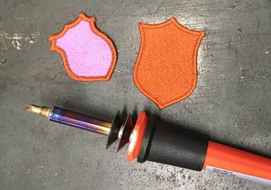
For more tips on patchmaking, please visit our website.
 The satin
border is one of the most versatile and easy-to-use stitch types. The shape is a
simply line, with no need to worry about inclinations. The border follows the
outline and has a width, much like a sewing machine. As a satin stitch, however,
there are numerous properties available for the satin border.
The satin
border is one of the most versatile and easy-to-use stitch types. The shape is a
simply line, with no need to worry about inclinations. The border follows the
outline and has a width, much like a sewing machine. As a satin stitch, however,
there are numerous properties available for the satin border.
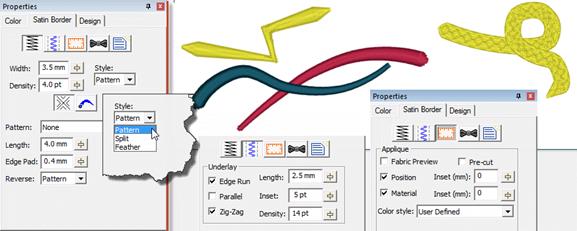
At the top of the property page there are separate buttons to
show the top stitching, underlay and applique properties. The top stitching is
composed of the width and density of the stitch, along with any variation in the
stitch width which gives a simple way for a satin border to approximate a
column, but without inclinations.
The Style of the border topstitch will have a smooth satin or
pattern, a split satin, which divides itself into columns, or a feathered-edge
stitch.
You can also adjust the line and nib style for open path
outlines. The line style varies the width over the length of the outline in a
manner according to the image displayed in the list box.
The nib is the shape of the endpoint. You can use the normal
squared-off satin end, or add a curved or tapered tip to either end for a more
finished look without the use of a column.
The border can have applique steps added to it, very much like
the normal Applique object type, the difference being that when using the satin
border type, you have much more control of the topstitch itself.
Please see the Satin Column section for information about the
patterns and underlay.
Tip: When using a wide border, use
a split (value of 2) with no reverse pattern to help prevent the stitches from
looping, while still maintaining the look of a satin.
 Satin
columns are versatile objects, and this property page allows you to use the
column in a few styles. “Normal” satin stitches are what you almost always think
of with satins; they go left-to-right and back again, making a smooth, narrow,
continuous stitch. But you also have the option for Contour and Fringe stitching
styles available.
Satin
columns are versatile objects, and this property page allows you to use the
column in a few styles. “Normal” satin stitches are what you almost always think
of with satins; they go left-to-right and back again, making a smooth, narrow,
continuous stitch. But you also have the option for Contour and Fringe stitching
styles available.
Pass Count
3 and 5 pass whip stitches are available to create more
texture. The thread does build up, but the program opens the density very
slightly to allow for it. The use case for this is to provide a more vintage, or
even simulating a handmade element in the embroidery.
Satin columns are one of the most-used stitches, and they have
a lot of properties available. The most important of which is the density.
Remember that density is measured in stitch points, which are tenths of a
millimeter. The bigger the distance, the lower the density. Normal density for
satin columns is 4 points to 5 points unless a fine thread and tightly woven
fabric are used. Often, the 5-point density is preferred as it will not push the
fabric around as much, and still provides nice coverage.
When choosing the patterned topstitch, a normal smooth satin
is the default, however you can adjust the patter to appear like a fill pattern
that curves with the stitching. Each pattern can have its stitch properties
adjusted. Stitch Length in the pattern relates to the size of the pattern that
is made. If you make your pattern too wide, it will not be visible unless the
satin itself is very wide. Here you can see how a satin pattern will turn with
the stitching:
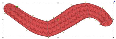
The Edge Pad is a means of protecting the edges of the
stitches from have excessive needle penetrations that can pull on the fabric and
pucker.
When patterning, the needle penetrations can lie next to one
another causing the fabric to lash or even cut. If this is a danger for the
fabric being embroidered, set the “Reverse” to “None” which means the pattern
will only occur on every other stroke of the satin. The pattern effect will be
lighter, but the embroidery will be better and the fabric will not have as many
cuts.
The pattern of the satin also has compensation and gradient
properties. Please refer to the Fill Pattern section of Fill Objects for images
and further description.
Compensation
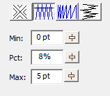
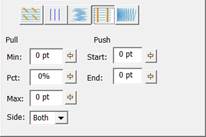
Left: Level 1 & 2, Right: Level
3
Compensation helps create embroidery
that matches the image, understanding that the process of sewing the design will
create distortion as it is happening. With compensation, the endpoints of
the lines in a fill are stretched out slightly past the edge of the shape. This
helps with registration issues because as the lines are sewn, the fabric is
pulled in slightly (shortened), so the longer lines will reach the spot intended
to be covered.
You can use a minimum value, usually 0 – 3 points,
depending on what the fill is lined up against. If your fill has a wide
difference in the width of the runs, in other words some narrow parts and some
fatter parts, you may want to use a percent for the compensation. We
suggest keeping it a small value, 2-3%. It will be kept in check by the Max
value though, even if you use a high percentage.
While the compensation numbers sound like something you should
use, they’re really there more for the professional who uses them all the time.
Most of the time, simply adjusting the shape to overlap anything that neighbors
it will do a fine job of handling registration issues.
The Side control in level 3 allows for control of which sides
the compensation will extend. Sometimes, a shape has been compensated under
another shape enough not to compensate it on one side, leaving the other side
open and needing some extra stitch length.
Push compensation will shorten the end of the column, as
thread tends to expand fabric along the line of the column, leading to
registration difficulties, particularly with outlines. Use push compensation
very sparingly.
Feathering
Feathering the edges of satin columns is a good way to
simulate animal fur. Overlap multiple layers to make a more realistic
appearance. In this example, three satin rings were set with feathered edges.
The rings sewed outer-to-inner, and overlap slightly.
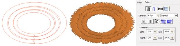
A split stitch in the column simply means that the needle will
land in rows, lengthwise along the column. You can set the number of split
columns, the minimal stitch value (to avoid fabric cuts) and you can avoid the
reverse stitch pattern, which helps preserve the look of the satin column. Here
is a column split into three:
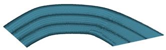
 Satin
stitches are good at covering the fabric, but they have challenges, especially
along the edge, where tightly placed dense stitches can penetrate the same hole
in the fabric or even cut the fabric. You may have sewn, for example a knit
shirt, and had the edges of satin stitches create holes in the fabric. For this
reason, a parallel or zigzag underlay is often used. It provides coverage while
pulling the fabric at slightly different angles and that can allow the top
stitching to have reduced density.
Satin
stitches are good at covering the fabric, but they have challenges, especially
along the edge, where tightly placed dense stitches can penetrate the same hole
in the fabric or even cut the fabric. You may have sewn, for example a knit
shirt, and had the edges of satin stitches create holes in the fabric. For this
reason, a parallel or zigzag underlay is often used. It provides coverage while
pulling the fabric at slightly different angles and that can allow the top
stitching to have reduced density.
Satin also has the issue of tension. Short stitches in the
same direction, laid next to each other, builds up stress in the fabric,
gathering it in toward the middle of the satin stitch. This can cause
registration issues with subsequent stitching. This can be managed by binding
the stabilizer to the middle of the satin with a center run, or a pair of edge
runs that travel just inside the shape. The edge runs also have the added
benefit of lifting the edges of the satin up, out of the pile of the fabric. For
these reasons it is not uncommon to use a medium density satin with a lot of
underlay.
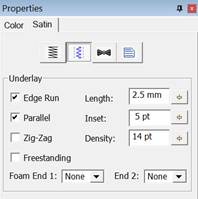
In the underlay properties, the “Edge Run” will create runs on
either side of the satin, just inset by an amount controlled by the Inset field
on the property page. The inset for the edge run is usually is set to fall just
inside the stitching – perhaps a half-needle with or slightly more, which allows
some relief around tight corners. The stitch length of the edge run is also
adjustable; use smaller stitches for tight, narrow columns and longer ones if
you want to reduce the stitch count, or are worried about cutting the fabric.
The default is usually sufficient though.
The density of the parallel and zigzag underlay is adjustable
for increased coverage. Sometimes it is better to have a higher density underlay
(0.8 – 1.2mm) and a lower density top stitch (0.8mm) so that the coverage is
solid, but the pull on the fabric is reduced, which helps with registration
issues (eliminating gaps between stitched areas).
Freestanding Underlay (Level 2)
The ‘Freestanding’ underlay creates a mesh under the satin,
similar to the freestanding background object type. This is useful when making
Richelieu bars or satin shapes that will be stitched on wash-away stabilizer.
When using the ‘Freestanding’ option, you do not need the other options, so you
can leave them off. The Length, Inset and Density properties do not apply to the
‘Freestanding’ option.
Foam (3D) Underlay (Level 2)
The ‘End 1’ and ‘End 2’ underlay properties control automatic
caps and joins for 3D foam embroidery. End 1 is defined on the outline as the
location of the closing point (red node). Note: Because the density required to
cut foam cleanly is so high, avoid turning tightly, as those stitches can bunch
up.
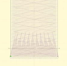
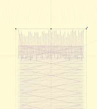
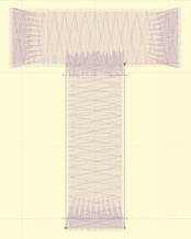
Automatic underlay shown,
left-to-right: cap, join, a letter.
The ‘Foam’ style automatically sets the underlay,
including end caps on both ends, sets compensation and increases the density so
that the 3D foam can be cut out by the needle.
Contour (Level 2)
Checking the ‘Contour’ button on a Satin Column will arrange
the stitches to run opposite to the inclinations, rather than parallel to them.
The density is maintained throughout the column, even if the column widens and
narrows, as the program will automatically adjust the number of rows as the
width changes. Contour 2 will provide more of a ‘fill’ effect as areas widen and
narrow, whereas Contour will have varied density across the shape as it
widens.
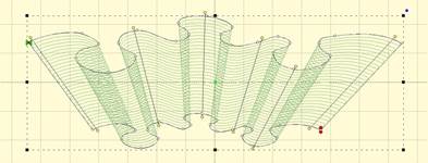
The Fringe stitch is a unique stitch that allows you to create
what some call “3D Embroidery” by cutting the bobbin threads under the satin,
which frees up one side of the stitching to come up and away from the
fabric.
This Fringe stitch lays a run down along the edge of the satin
first, and then places the satin over top with extra needle penetrations causing
the satin to anchor itself to the run. It finishes off with a top stitch run to
anchor it all together. This method allows you to have fringe effects in
embroidery without the need to anchor the stitching down with a fill, as has
always been the case.
Now that we have covered outline basics, it’s time to discuss
Satin Columns. Satin Columns have stitches that go across the shape from left to
right forming a smooth, possibly curving, filled area. Satin columns are also
referred to as “Turning angle fills” sometimes. Satins are generally the second
most important stitch type you will use, after Runs.
Because we tend to think of satins as going ‘left-to-right’ or
‘side-to-side’ there are special input methods for them accommodate this.
Satin columns are special because in addition to the shape
itself, you’ll need to add incline lines to get the column of stitches to curve
nicely. The incline lines are the direction the stitches will lay on the
fabric.
Incline Lines
 Before we
can discuss the input methods of satin columns, we need to go over incline
lines.
Before we
can discuss the input methods of satin columns, we need to go over incline
lines.
When you have a shape drawn that will be a Satin Column, you
will need one or more incline lines, also called, “Inclinations.” When you first
draw the shape, the program attempts to provide a satin stitch automatically,
based on the shape. If this is acceptable, you can skip adding your own.
The incline lines input can be started using the ‘i’ key or
the Inclines button on the Tool Pane. To add an incline line, simply begin on
one side of the shape by clicking down, and then drag the mouse across the shape
to the other side. When you release the mouse button you will have added an
inclination line to the shape. You can repeat this drag operation to make as
many incline lines as the shape requires. When you are finished, simply right
click to exit the mode.
How many incline lines do you need? That is a great question,
and like a haircut the answer lies in the form of a question, “How does it
look?” Simple lines of satin stitching might only need one or two inclines. But
if you curve around, you’ll need one whenever you make a quarter-circle, or
whenever you want to switch from turning left-to-right or vice-versa.
Generally, start with a pair of inclines at the ends, and at
least one in the middle. As you add inclines, you will see the stitches change.
You can stop anytime you are happy.
If you make a mistake, you can exit the Inclines mode, and
then simply drag the endpoints of your inclines around. You can also drag one of
the points to the opposite side to remove the incline. You can also go back and
add, remove or move the inclination lines at any time, which is handy if you
decide you need to edit the shape later.
When a shape turns, one side will be longer than the other.
This means that one side will have its stitches closer together than the other.
Another way to say this is that the density (stitches per inch) inside the turn
is higher. When the satin stitch is created, it is given a specific density to
maintain – and that is on the outside of the turn, not the inside. The
program will do things on your behalf, such as short-stitching, to minimize the
impact of the increased density on the inside of turns. But you can also help by
looking at what is going on, and making changes to the inclinations so that the
density increase is minimized.
Tip: When turning around a tight
corner, you might want to begin ‘leaning’ into the turn, which helps the
stitches go around with less bunching:
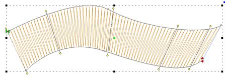
Another issue to look at when adding, or adjusting,
inclinations is smoothness of the change in angle. You don’t want your
inclinations to be ‘wobbly’:
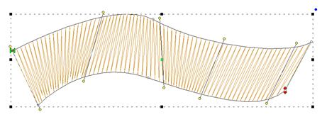
When going ‘around’ a large curve, imagine a center point, and
incline as if there were rays radiating from that center point:
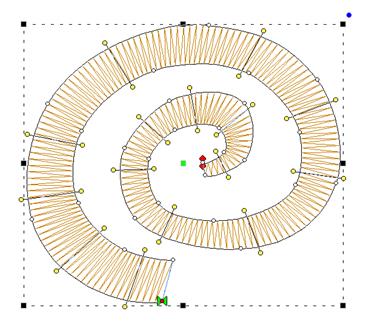
The smoother you change the angle in your satin objects; the
smoother the sewn result will appear.
Inclines at ends of satins
Satin objects are like any other – they have a shape. It is
the inclination lines that define that shape as a satin. This has some
noteworthy effect on the ‘ends’ of the shape, because, naturally, shapes don’t
have ends; people perceive them though.
In the picture below, what do you see?
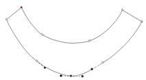
Perhaps a rudimentary smile? And what are the ‘ends’? If we
asked a thousand people, they’d all tell you the same thing. The ends are the
flat sections, right? Therefore, the natural idea is to have inclinations that
parallel those lines.
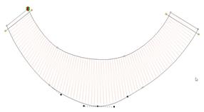
In fact, this is how inclines work, with respect to the shape.
Once the last incline is ‘seen’ the program keeps the angle the same, regardless
of the shape:
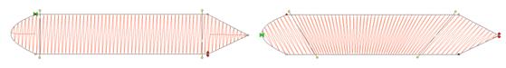
Sometimes you will see stitches ‘diving’ into corners. This is
because the shape, past the incline, looks pointed. In this image, the incline
on the left is parallel to the points ending the shape, but the incline on the
right is not:
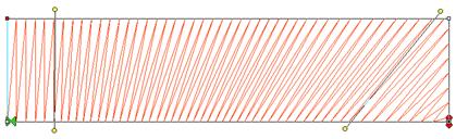
The program will look for two
corners, and find them if they make a line that is reasonably parallel with the
ending incline. If they’re not found, then the stitches just keep going at their
current angle, whatever that may be.
Note: You can adjust incline points by dragging them. If
you hold the shift key down while dragging an incline endpoint, the other side
of the incline line will move with it.
Sides A/B Method
 This
method of input uses the knowledge that the satin stitch will have two ‘sides’,
and you draw each one separately. This method of input is easier for some types
of art where it may be that you want to add the incline lines after the outline
has been drawn. To use this mode, first, select the ‘AB’ input method from the
Tool Pane. Then select an input method that you will use. Generally, the Point
or Freehand inputs are chosen.
This
method of input uses the knowledge that the satin stitch will have two ‘sides’,
and you draw each one separately. This method of input is easier for some types
of art where it may be that you want to add the incline lines after the outline
has been drawn. To use this mode, first, select the ‘AB’ input method from the
Tool Pane. Then select an input method that you will use. Generally, the Point
or Freehand inputs are chosen.
The first side, usually thought of as the ‘left’, is now
drawn. Once you get to the end of it, right-click the mouse. Instead of closing
the shape, this now starts you drawing the other side. You can draw from the
second side’s ‘end’ toward the ‘start’, or go back and make the side going
‘forward’, similar to the way you made the first side. The program will figure
out which way you are drawing it.
Once you have drawn each side, right click again. The shape
itself will now close and you will be put into the input mode to add Incline
lines. Drag the desired incline lines across the shape, and right-click to
finally generate the object.
To sum up:
1.
Draw side ‘A’. Right-click.
2.
Draw side ‘B’. Right-click.
3.
Add incline lines. Right-click.
This method of input is useful where the Left/Right method
cannot make the shape:
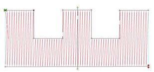
Sides Left/Right Method
 This
method of creating satin columns creates the shape and the incline lines at the
same time. Selecting this mode also forces you into the Point mode for entry,
because the only way to create alternating points on the sides of the satin is
by clicking.
This
method of creating satin columns creates the shape and the incline lines at the
same time. Selecting this mode also forces you into the Point mode for entry,
because the only way to create alternating points on the sides of the satin is
by clicking.
What you’ll do is create the outline by clicking a point on
the ‘left’ side of the satin column, then a point on the ‘right’ side. You keep
going, left, right, left, right until you have completed the shape. It will look
like you have drawn a ladder.
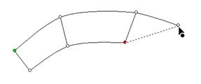
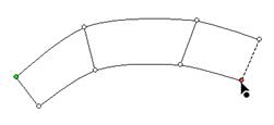
As you make each pair of left and right points, you are not
only defining the shape of the column, but also adding incline lines across each
pair of points at the same time.
As with Point Input mode, you can create curves by
left-clicking, lines by ctrl-left-clicking and cusps by shift-left-clicking.
When your shape is complete, right-click to end the input and
generate the object. The shape can now be edited if necessary. Note the inclines
here can be manipulated as if you drew them individually. There is no difference
in this style of input from any other, other than how it is drawn. One benefit though is that the inclines at the ends will
line up to make a straight edge that goes all the way across the shape.
When entering a curve, as you click along try to imagine the
curve as going around a center – as you click, each pair of points should point
toward that center.
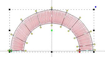
Creating corners with satin columns is a bit of an art. When
creating lettering for example, the cornering methods you use will radically
affect how the viewer of the stitched item perceives your embroidery.
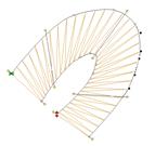 The simplest
form of cornering is to simply turn, with inclinations going around the turn.
When making a hard corner, this results in stitches pivoting around the inside
corner of the turn. If you’re going to turn this way, try beginning to ‘lean’
the stitches into the turn, and when coming out of the corner, give them some
chance to ‘lean back up.’
The simplest
form of cornering is to simply turn, with inclinations going around the turn.
When making a hard corner, this results in stitches pivoting around the inside
corner of the turn. If you’re going to turn this way, try beginning to ‘lean’
the stitches into the turn, and when coming out of the corner, give them some
chance to ‘lean back up.’
Surprisingly, most of the time, professionals prefer to simply
turn corners instead of using more complex corner styles, which we’ll describe
next.
Letters often look better with a set of satin columns, rather
than turning around hard angles. One method commonly used is with three satin
columns: and entry, and end ‘cap’, and the exit stroke. A typical example is
this letter ‘A’:
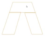
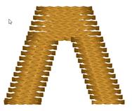
You’ll see that the cap angle is as ‘flat’ as it can be so
that the stitching is smooth. For registration purposes, you may want to overlap
the cap on top of the entry column. And the exiting column usually is best to be
snug against the cap. In the illustration on the left, notice the slight overlap
of the left column and the cap – barely a stitch is typical.
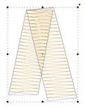
A hard corner may not be appropriate for a cap. And it may be
so tight that it cannot turn reasonably. In this case, break the column into two
and overlap the corner. Don’t worry about the stitches overlapping each other,
as satin stitches sew quite well even when overlapped. If the density is not too
tight for the thread and fabric, you can even get a blended look.
Mitering
Mitering is a form of overlapping where the exiting column
starts at a ‘point’ and widens out as it leaves the corner. This makes the
stitching resemble a picture frame:
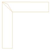
Mitered corners work well for corner angles at 90 degrees,
like a picture frame. Hard turns cause longer miters, which have too many small
stitches, and shallow turns do not need mitering.
You will probably be creating lettering at some point, which
constantly joins satin columns. But many other design types require this as
well.
When columns meet up at nearly right angles, there can be a
gap that forms as the fabric is being ‘parted’ in two opposing directions.
Sometimes you can overcome this by stretching the later object so that it comes
slightly over the earlier object. When doing this, you only need a few stitch
points of overlap. As the stitch forms on top of the earlier column, the stitch
will ride down and seat quite well, filling the gap.
Sometimes you have meeting columns that have low enough
density that there will be something of the fabric visible. If you need to
completely cover the fabric, insert a set of stitches as a separate object as a
form of underlay. Usually, you will do this with the same angle as the early
column will stitch. This acts to bind the fabric down and provide the color
needed when the columns intersect.
As in the case of a letter ‘k’, sometimes satins will come
together at acute angles. You might have the impulse to attempt to turn the
joining column. Sometimes this will work, but there is another way: Simply keep
the angle constant, and overlap the joint. The ideal situation is where
you have the acute angle column being sewn before the straight one. This allows
for easy (and greater depth) or overlap.
Where the part that is coming in at a steep angle will be sewn
later, the joint is more difficult, but works the same. You simply have to be
careful about your shape. Sometimes this is the case where turning the angle
near the end can be helpful for a smooth joint.
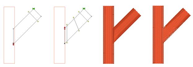
As with right angles, the use of an underlay object can
provide better coverage, and make the joint easier to accomplish.
When creating a shape like a simple letter ‘T’ you can do it
with two objects. Assume the vertical stroke comes first for this example. Let
the Exit point of the stroke occur naturally – at the top, on one side or the
other. Then, make the horizontal top column. Set the Entry point of the top
column to match the Exit point of the upward stroke. This allows for continuous
sewing. You still may want an underlay object, in addition to the underlay
provided by the objects themselves, but the simplicity of the connection is nice
to understand. Also, if the design permits it, ending the pattern in the inside
of such a corner as where these two strokes meet allows for tie-off stitches to
be nested nicely, and in fact they also double as color fill in the
intersection. A lot of ‘old school’ embroidery fonts were digitized this
way.
Sometimes you have to cross over an earlier stroke. This is a
common problem when digitizing a Celtic knot, which has art that goes
over-and-under repeatedly. One trick that is used is to have the Exit
point of one stroke align with the Entry point of the column that is going to
pick up on the other side. This means an exposed connective stitch will go
across the ‘Over’ column, but its angle will be similar to the angle of the
satin stitches that it is going across, thus it blends in. As long as the stitch
will be short, usually under 3mm, you can avoid adding an object for it.
Otherwise, simply add a Manual stitch object with two points, and make sure you
go the right direction across.
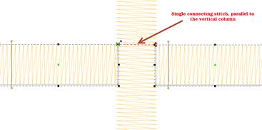
Satin stitching is hard on fabric; it pulls the fabric, it
pushes the fabric, the needle comes down so close as to cut it sometimes. Narrow
satin stitches are the worst, as the fabric is pulled tightly under the tension
of the thread, and the needle comes down in a very dense pattern. Depending on
the fabric you are embroidering, a narrow column of stitches (perhaps as wide as
1mm) can be too much stress for the fabric and can cause puckering or gathering.
A more generous 1.5mm of travel is preferred. This mean that any ‘points’ in
your shape will want to be clipped a bit so that the stitch has a bit of travel.
If you are wondering what 1mm looks like, it is slightly wider than the needle
you are embroidering with. If you think about it, a needle width isn’t a lot,
but giving the extra length of stitch can do quite a bit for the sew-ability of
your design.
Sometimes your column will narrow down toward a point, and
there is some relief that can be given here with inclinations. If you angle the
stitching slightly as it comes into the point, the stitches stay a bit longer,
while the column continues to narrow. This effect is known as chiseling, and it
is effective.
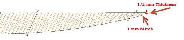
Also, narrow satin columns will appear to be of a higher
density when sewn, so you may want to open up the density a bit.
Note: The program will
automatically loosen the density as the shape narrows.
Also be aware that narrow satins will not register as well as
wider ones against other stitching. When creating a satin border, try widening
the stitch a bit and overlapping the adjacent stitches. This will help prevent
gaps without requiring additional stabilizer.
 A Fill is
a repeated run stitch back-and-forth in rows, used to cover a large area. There
is a lot of terminology associated with fills, such as “complex” (it can have
holes), “Tatami” or “Ceeded” (The runs are offset so the rows don’t line up),
“Edge Travel” (the stitches run along the edge instead of under the rows),
etc.
A Fill is
a repeated run stitch back-and-forth in rows, used to cover a large area. There
is a lot of terminology associated with fills, such as “complex” (it can have
holes), “Tatami” or “Ceeded” (The runs are offset so the rows don’t line up),
“Edge Travel” (the stitches run along the edge instead of under the rows),
etc.
The main issue is density, or the distance between rows, and
here is where you get to make a decision. When a fill executes, it puts a lot of
stitches into the fabric. Those stitches displace the fabric somewhat, just like
when you get into a bathtub, the water has got to go somewhere – stitches in
fabric are the same. So, the more stitches you put into the fabric, the ‘bigger’
the fabric has to become to handle it.
Remember that density is measured in stitch points, which are
tenths of a millimeter. The bigger the distance, the lower the density.
In the past, the typical production method was to use a
cut-away stabilizer that can hold together with a lot of stitching in it, which
relieved the fabric considerably. Then, the designer could use densities of 4
points or even tighter, thus creating “full coverage.” Full coverage means
the fabric does not show through. It sounds good and if you’re being paid by the
stitch, it is great. But what if you want the fabric relaxed, not stiff as a
board? And full coverage isn’t as important as wearability and softness? Then
plan on releasing some of the density. Go for 5-point density or even lower.
There are other options too. Using two fills, in
different directions, but each with only half the density, you can create a far
more stable fill with less displacement. And the coverage works out quite
nicely.
If your fill sews out like a soup bowl, indented and firm, you
needed less density and more stabilization.
When a fill executes, it does so in sections. This is driven
by the shape of the object, and where the Exit point is located. When the fill
has to travel between those sections, it can either run under the rows of
stitches that haven’t been filled yet, or it can run along the outside edge of
the shape.
If the fill is a normal density, even, one of the lighter ones
previously discussed, the traveling runs probably will not be visible and
certainly not noticeable, so the most efficient thing to do is let the fill
travel normally.
There are uses for fills that have much wider spacing between
rows; trapunto effects for example. In a fill that has low density – where the
stitches are really far apart -- you may want the traveling stitches to go along
the outside of the shape, rather than under the rows where they would interfere
with the desired visual effect. This is accomplished by checking the ‘Travel
edge” box.
A fill has a single angle at which it runs. You can add an
inclination using the Incline button on the Tool Pane.
When choosing the patterned topstitch, a normal fill (tatami)
is the default, however you can adjust the pattern to have needle lands that
form texture. Each pattern can have its stitch properties adjusted. Stitch
Length in the pattern relates to the size of the pattern that is made. If you
make your pattern too wide, it will not be visible unless the shape itself is
wide enough. To make a fill appear smoother you can also add randomness to the
needle lands for a Tatami fill.
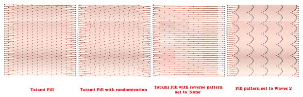
Note: There is also an option of
using fill pattern “None” which will emulate a satin. This is for very small
areas, where the stitches will not be excessively long, or for fills that are
only going to be carved.
The Edge Pad is a means of protecting the edges of the
stitches from have excessive needle penetrations that can pull on the fabric and
pucker.
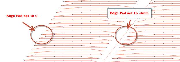
When patterning, the needle penetrations can lie next to one
another causing the fabric to lash or even cut. If this is a danger for the
fabric being embroidered, set the “Reverse” to “None” which means the pattern
will only occur on every other stroke of the satin. The pattern effect will be
lighter, but the embroidery will be better and the fabric will not have as many
cuts.
Compensation in fills is very similar to compensation on satin
columns, which has been described earlier. Unlike columns, however, there is
rarely a need for extra control such as side selection or push.
Fills can have curved rows of stitching, not only straight
ones. Switching to a curved fill is done with the “Curved” checkbox. When you
select the fill to be curved, a curved line, similar to a break line, will be
created for you automatically, and it will be angled as your inclination was
previously.
You adjust the curve as you would with any line. You can add
points and remove them. The curve is fully adjustable, but realize there are
some rules you should follow.
1.
The endpoints of the curve should go past the edges of the shape.
2.
The curve needs to be simple – making a loop may be fun, but it won’t be nice to
sew.
3.
Hard turns will give you areas of low density on the angle, and high density as
they straighten out, so use things like that with low density as second fill,
for texture and dimension.
Here are some examples of curving fills in action. The
stitches and the outline are shown side-by-side for each. Notice the curve on
the right has an additional node added to produce an ‘S’ curve:
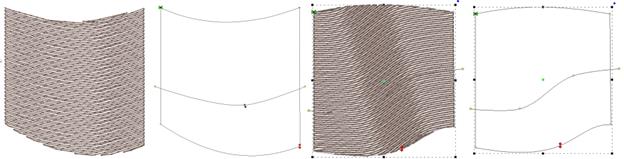
When you click off the curved fill, the line will be replaced
with an inclination.
Gradient (Level 2)
The density of the fill can be adjusted so that each line of
stitching moves farther apart from the previous line, which makes for a varying
density, called a “Gradient.” Gradients are an effect, and not used to provide
coverage as a regular fill might. When making a gradient, you have two
densities; the starting density, which is the one set for the fill, and the
final density, which is the one set in the Gradient property. The gradient can
have different styles selected using the list box. Note that a standard fill has
a gradient set to “None.”
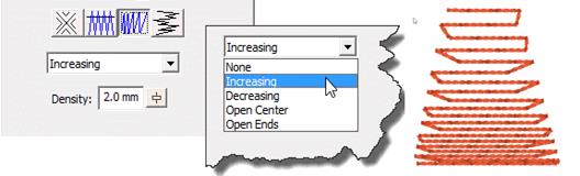
Feathering is the extending and shortening of the edges of the
fill in a random manner. This is used in fills that are adding texture to a
design, and generally would be used over some other design objects for
coverage.
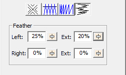
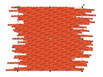
You can adjust independently the left and right inside
feathering and outside feathering values. By feathering the edges, you can
create simple fur effects.
When setting feather options, realize that left and right are
subjective, and if you edit the outline after making this setting, those could
actually switch.
 The
freestanding background has been used to simulate lace for many years. It
consists of diagonal runs of stitching that stitch over themselves in order to
lock in the stitches. Using only wash-away stabilizer as a base, the
freestanding background can remain as-is, with no fabric, or as a support layer
for satin and fill stitches. Often, a shape made with the freestanding
background, and some clever inclinations on top-stitch satin columns, can be
made to stand all by itself as lace.
The
freestanding background has been used to simulate lace for many years. It
consists of diagonal runs of stitching that stitch over themselves in order to
lock in the stitches. Using only wash-away stabilizer as a base, the
freestanding background can remain as-is, with no fabric, or as a support layer
for satin and fill stitches. Often, a shape made with the freestanding
background, and some clever inclinations on top-stitch satin columns, can be
made to stand all by itself as lace.
In the example below, the heart came in from the library and
was set to freestanding fill. The ‘Diamond’ checkbox was set and the color
changed to create the middle heart. The outline was added by copy and paste of
the shape, inflate to reduce its size so the stitches would sit on the
background, and the stitch type was set to Satin Border, with all underlay
turned on.
Another alternative to the ‘Double’ pass is a single. This
creates nice parallel rows of stitching which work for quilting effects, such as
sewing rows in a grid on linings, or as background quilting in an In-The-Hoop
project, etc.
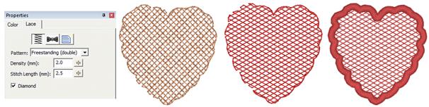
Motif Fill
Objects
 Motif
fills are similar to regular fills. You control the density and gradient. Motif
fills can be curved as with regular fills. In motif fills, the traveling
stitches always run along the edge so as not to interfere with the motifs. The
motifs are added in the same manner as motif runs.
Motif
fills are similar to regular fills. You control the density and gradient. Motif
fills can be curved as with regular fills. In motif fills, the traveling
stitches always run along the edge so as not to interfere with the motifs. The
motifs are added in the same manner as motif runs.
The density adjustment in motif fills adjusts spacing between
each line in the fill. A zero value here will cause each row to just touch the
previous row.
Please see the Motif Run section for details on the use of
motif controls.
 Applique
Objects have “Position”, “Material” and top stitching steps. The use of the
steps is optional, including the top stitch. Here is a general way that applique
is typically machine embroidered:
Applique
Objects have “Position”, “Material” and top stitching steps. The use of the
steps is optional, including the top stitch. Here is a general way that applique
is typically machine embroidered:
The “Position” step places a run down on the fabric, and then
stops the machine. This is used to provide you with a placement line for your
applique. You can use a Pre-Cut applique, perhaps cut with a machine, or by hand
using a template. Or you can simply lay down a piece of fabric big enough to
cover the placement stitch. A tip to placing your applique is to use some
adhesive, spray-on, iron-on or otherwise, to hold the applique fabric in place
when the machine is restarted.
The “Material” step will sew another set of running stitches
to anchor the applique fabric in place. This step may be omitted if the applique
is Pre-Cut, as the topstitching will anchor the fabric down.
The topstitch finishes the edge of the applique, and you can
choose from Blanket Stitch, E-Stitch or Satin Border.
Note: You can also use the Satin
Border object type to make appliques, and it provides additional
properties.
The applique properties add applique steps and visualization
to the object. You can select adding a “Position Stitch” which will be a single
run that sews out to indicate to the user where the applique will be laid. Then
an optional “Material” run can be done to anchor the applique in position.
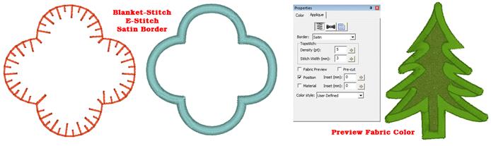
Blanket and E-Stitch have stitch length and width that can be
set in the properties. The Satin and Zigzag stitches use density and width. The
applique can have a fabric preview that lets the user visualize the final
applique with colors similar to those that will actually be used. The color used
for the preview is set by the color of the Position step.
The Pre-Cut checkbox indicates that you will have the applique
already cut, and this causes the object size to be locked, preventing you from
inadvertently mismatching the design and the fabric. Pre-Cut appliques could
also come from dies, where the exact size of the applique is known in
advance.
If you scan in a precut shape to create an applique, such as
from a die-cut fabric, place the fabric on a background grid with known
measurements – for instance 10mm or ½”. Using those measurements, you can scale
the image to match the grid in the program, so that the size will be exact.
Sometimes, a scan may have a vertical or horizontal difference in scale (it can
stretch the image) but the grid you scan in will show you that, if you use the
measuring tool on the main toolbar.
Applique insets are used to offset the stitching from the
applique material itself. If the material or top stitch was identical in size to
the applique (if it is pre-cut especially) then the applique might not be well
sewn down and could lift away from the finished product.
The Color style allows users to adjust how they work with
color during appliqué steps. There are three styles: Keep Color, PES Card
(Traditional) and User Defined.
Use Keep Color to conserve thread changes by combining like
colored Top Stitch and next position placement stitches. This will allow
the machine to stitch the finishing stitch of the piece and the placement stitch
of the next piece (if the same color) without having to start the machine
again.
For traditional stops after each section, you may select the
PES Card option from the Color type list. This selection may be necessary
depending on your machine, particularly if you use PE-Design / Palette or
similar to write a PES card for your machine.
The User Defined lets you use any color you want.
More on Applique
In the Color Properties you can click on a color to change it,
and this displays the Thread window, which also has an “Applique” tab. Using
that tab, you can save a cutting file for virtually any cutter.
StitchArtist also enables you to mix an image into your
applique, making mixed-media applique a unique option for your projects.
Please refer to the Applique
section in the Embrilliance Platform.
 Stippling
is a wandering path that is formed automatically based on an outline and any
number of holes. The path is a continuous curve that wanders around seemingly
aimlessly yet it meets itself at the finish. Because the result is a closed
shape, the Exit point is ignored, but the Entry point is honored. The Stippling
object can have a single inclination line added to it which will set the
rotation of the pattern (So that it comes off horizontal) so that different
blocks will have even greater differences in pattern.
Stippling
is a wandering path that is formed automatically based on an outline and any
number of holes. The path is a continuous curve that wanders around seemingly
aimlessly yet it meets itself at the finish. Because the result is a closed
shape, the Exit point is ignored, but the Entry point is honored. The Stippling
object can have a single inclination line added to it which will set the
rotation of the pattern (So that it comes off horizontal) so that different
blocks will have even greater differences in pattern.
There are four patterns that you can choose from with
stippling: Drunkard, which wobbles a bit and is slightly inconsistent with the
distance between jigsaws, Curvy, which has a ‘cleaner’ and more consistent
spacing, Leafy, which tapers some of the pattern to give a floral effect, and
finally, Geometric, for a cleaner look perhaps for modern quilting.
With all of the patterns you can adjust the spacing of the run
to vary from a tight stipple to a loose meander. You can also set the stitch
length.
If you want to edit the path or change the stitching in more
ways, the stipple can be converted to a run, which will keep the generated path,
and let you apply stitch effects such as motif. Simply click the Run stitch type
button in the Tool Pane while the stipple object is selected.
Cross Stitch objects create patterns of crosses in filled
objects and on outlines to resemble handwork.
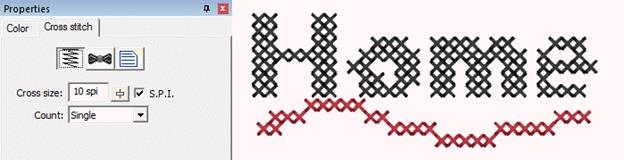
The cross size is available in metric and Stitches per Inch
(SPI). Stitches per inch settings are not exactly duplicable in normal metric
stitch points – and the result is obvious if stitched on Aida cloth which is
woven at densities of SPI. Therefore, you have your choice of how the cross-size
works.
When creating a cross, each leg of the cross is stitched
twice. Sometimes you will want more thread, for example when using large
crosses, and you can adjust the count setting accordingly. Realize that
increasing the pass count will have a dramatic effect on the stitch count.
The cross stitches for all cross-stitch objects are made on a
default grid of cells. This allows the stitching of adjacent object shapes to
line up. We think of each of these cells as either ‘off,’ meaning no cross, or
‘on’ meaning a cross will be stitched.
When creating outlines with closed shapes, only the cells that
have their center within the shape will be set to cross. If you make a shape
that appears to ‘miss’ a cell, and you want to make it appear, it is normal to
adjust the outline shape accordingly. When adjusting the shape to turn on (or
off) a cell, we suggest adding one or more line nodes to the outline (ctrl key
while clicking in point mode.) We also suggest using the Spline mode for point
entry because it can make it easier to insert points to grab specific cells.
When creating crosses with an open object, whichever cells are
intersected by the line are turned into crosses.
If you move an object, the crosses will move with it. Once
moved, you may want to re-generate the object (touch a property or outline node)
so that the correct crosses, exactly on the grid, will be generated.
 Contour
Echo is a stitch type for quilting, trapunto or decorative effects. It provides
different ways to echo around outlines and holes. When echoing, you can set the
distance for the echo in mm and also see it in stitches per inch. There can be a
gradient to the echo, and using the stitch properties button at the top of the
Echo properties page you can set the stitch style to several of the Run stitch
types.
Contour
Echo is a stitch type for quilting, trapunto or decorative effects. It provides
different ways to echo around outlines and holes. When echoing, you can set the
distance for the echo in mm and also see it in stitches per inch. There can be a
gradient to the echo, and using the stitch properties button at the top of the
Echo properties page you can set the stitch style to several of the Run stitch
types.
You can choose from three styles:
1.
Echo Outline Inward, which creates an interesting echo inside the shape.
2.
Echo Interior Clipped requires any number of holes and will echo those out
toward the outline. The shape of the outline is used to clip or cut the
echoes.
3.
Echo outline outward is a simple echo of the outline itself. You can echo as
many steps as you choose.
The Contour Echo can be converted to a series of Run objects
for further editing as desired by clicking the Run stitch type button in the
Tool Pane.
 Program
Motifs are items that the software knows how to digitize, and unlike a regular
motif, it will do so differently depending on the size of the design. Program
motifs include French knots, candlewicks and eyelets (Level 3).
Program
Motifs are items that the software knows how to digitize, and unlike a regular
motif, it will do so differently depending on the size of the design. Program
motifs include French knots, candlewicks and eyelets (Level 3).
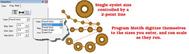
Program motifs follow the same drawing methods as a run, but
given their size, making hard points obvious is difficult. They can run along
outlines of shapes, or be used singly with short line segments. Due to their
nature, they tie themselves in and out, so you could trim between if
desired.
The Single eyelet size is controlled by making a two-point
line. The starting point will be the center of the eyelet, and the second point
will be the outer radius of the eyelet.
The only real consideration when using these stitch types is
that knots are dimensional and have been programmed to emulate their hand-stitch
counterpart, therefore they tend to produce a lot of stitches.
Converting objects to different stitch types is as easy as
selecting the object and clicking on the desired stitch type. All properties are
lost when converting types; it’s like starting with new artwork.
Specialized Conversions
There are two conversions that are different than normal
conversions, and those are Stipple and Echo. Converting Echo or Stipple to
anything other than a run operates normally; the outline and any holes are
preserved.
Stipple to Run
When using stipple objects, there are times you wish to adjust
the generated pattern, or apply motifs to the run. When you convert a stipple
object directly to a run, the result is a run that has the path of the stipple,
not the outline that was used to create it. That result can be turned into a
line, motif or anything else.
Echo to Run (Level 2)
When converting Echo to run, the result will be one or more
objects that are the echoes. You can then apply any stitch type to those objects
for your desired effect.
As discussed in the Lettering section, you can design
templates for lettering to use in name drops, word walls, subway art, etc.
Templates are interactions between two different elements: A lettering design,
and a template object. To accommodate multiple template designs on a page, the
template and lettering items are named using a numbering system that will match
them together.
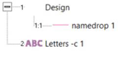
The simplest of the template forms is a namedrop. It is a
simple 2-point line, running left to right, that controls where lettering will
be placed.
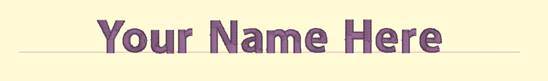
Namedrop lines should only have two endpoints, but they may
create a curve.

Envelope
Envelopes can yield effects from simple placement to
re-shaping of the lettering.
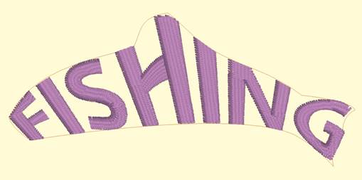
Envelope creation requires some specific knowledge. Envelopes
are closed shapes and have definite sides. A simple template form can be
described by a rectangle drawn clockwise, beginning at the top left corner. That
top left part is important as it marks the beginning of the envelope top.
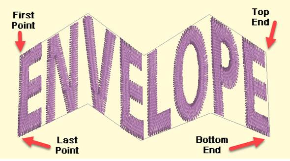
The template needs to understand a ‘bottom’ and a ‘top’. Thus,
it will have two sides, which are made up of normal straight-line nodes. To draw
an envelope, start at the top left point, which becomes the start of the ‘top’
of the envelope. Draw across the top and end the top line with a node that’s
either a straight-line point or a cusp point.
Next the right side is drawn by adding a line point below the
last top point. This marks the rightmost end of the bottom of the envelope.
Continue working on the bottom of the envelope working left toward the left
side. When you reach the left side, close the shape, which will
form that left side.
The top and bottom do not have to line up vertically. This is
used to stretch or shear (slant or italicize) the lettering.
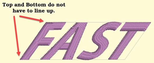
Baseline
Baselines provide a means for lettering to follow on a path,
whether open line or closed shape.

Baselines can be virtually any shape you make.
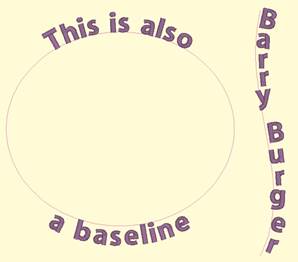
You can achieve any letter placement with a baseline. Even
‘wavy’ vertical text can be accomplished using a vertical line and rotating the
letters using the center rotation handle.
StitchArtist allows the display of all hoops in the platform,
including multi-position hoops. The multi-position hoops are not there to
automatically split. Their inclusion is for the purpose of creating designs
specifically for those hoops. As you are in control of all stitch objects, you
decide what parts of your design will go in each hoop section.
We suggest creating a separate design for each hoop section.
If the hoop you are using is not a physical multi-position hoop, you will need
to add alignment lines that exist on each design so that the position of the
designs can be lined up by the embroiderer when sewing.
As each design will center when it is saved, we suggest using
a basting box for each hoop position. The box should be centered in the hoop
section, and should completely contain your design section.
Once you have each design created, copy them to a separate
design page and save them individually. As this is an advanced topic, you may
want to look online for specific instruction.
Delayed Generation
 When you
tell an object that it is to be a certain stitch type, the stitches will
automatically generate. Also, when you adjust or edit the object, the stitches
will generate for you. But what if you want to do a complex series of edits on
the object? It might be desirable to turn the automatic generation off for a
while. You can do this with the ‘Delayed Generation’ button. As long as the
button is pressed, and you are in ‘Create’ mode, your stitches will not
generate.
When you
tell an object that it is to be a certain stitch type, the stitches will
automatically generate. Also, when you adjust or edit the object, the stitches
will generate for you. But what if you want to do a complex series of edits on
the object? It might be desirable to turn the automatic generation off for a
while. You can do this with the ‘Delayed Generation’ button. As long as the
button is pressed, and you are in ‘Create’ mode, your stitches will not
generate.
Generate Now
 When you want to generate
stitches on an object or set of selected objects, click the ‘Generate now’
button. If nothing is selected, the program will look for any objects needing to
be generated and will generate them accordingly. This button is useful when
Delayed Generation is turned on – you control what gets generated and
when.
When you want to generate
stitches on an object or set of selected objects, click the ‘Generate now’
button. If nothing is selected, the program will look for any objects needing to
be generated and will generate them accordingly. This button is useful when
Delayed Generation is turned on – you control what gets generated and
when.
Default Drawing of Line/Curve
 The usual mode of drawing with
points is to draw with curved points and use the Ctrl key to draw a line. This
may be undesirable for some art. You can use this button to switch the way that
operates – pressing it will cause drawing to default to a line, and the Ctrl key
will cause points to be a curve. Note that using the Shift key to make a line
constrained to 15-degree angles will work either way – you can constrain the
line angle as long as you are not making a curve.
The usual mode of drawing with
points is to draw with curved points and use the Ctrl key to draw a line. This
may be undesirable for some art. You can use this button to switch the way that
operates – pressing it will cause drawing to default to a line, and the Ctrl key
will cause points to be a curve. Note that using the Shift key to make a line
constrained to 15-degree angles will work either way – you can constrain the
line angle as long as you are not making a curve.
Auto-scroll Toggle
 When drawing, the edges of the main
view have an area that act as an auto-scroll area – if you move your mouse in
that area while drawing your page will scroll automatically which gives you more
room to continue drawing. Sometimes this is undesirable, and the action can be
toggled on and off using this button. Note you can also use the arrow keys while
drawing to scroll 1cm per key click. And holding the spacebar will let you pan
the screen by dragging it with the mouse.
When drawing, the edges of the main
view have an area that act as an auto-scroll area – if you move your mouse in
that area while drawing your page will scroll automatically which gives you more
room to continue drawing. Sometimes this is undesirable, and the action can be
toggled on and off using this button. Note you can also use the arrow keys while
drawing to scroll 1cm per key click. And holding the spacebar will let you pan
the screen by dragging it with the mouse.
When an object is selected, you can select all other objects
using the same style or stitch type by adding the Control key to a right-click.
Ctrl-Rt-Click > Select by…
Carving lines
 Areas filled with stitches such as
Satin Columns and Fills can be given additional texture using Carving Lines.
Carving lines are additional shapes that can be added to objects in a very
similar manner to adding holes. Use the ‘Add Carving Line’ button on the Tool
Pane to begin a carving line, and select the input method (usually Point Input)
to begin drawing. Draw a path over the object.
Areas filled with stitches such as
Satin Columns and Fills can be given additional texture using Carving Lines.
Carving lines are additional shapes that can be added to objects in a very
similar manner to adding holes. Use the ‘Add Carving Line’ button on the Tool
Pane to begin a carving line, and select the input method (usually Point Input)
to begin drawing. Draw a path over the object.
The carving line generates needle penetrations where the
normally-generated stitches intersect the carving line.
The only real caveat to carving lines is that in high-density
areas, your fabric may lash up as the needle is penetrating closely together.
For this and other reasons, some designers create two areas of fill, overlaid on
one another, each at half density. This adds texture, can reduce fabric pull,
and carved lines will add minimal impact.


Using Styles
Styles allow for repeated use of properties on a given type of
object. There is a style button on the top, right of each object property page.
When an object has been assigned a style, that style will be highlighted in the
style list, shown on the Style properties for the object. If an object was
assigned a QuickStyle, but has been modified, it will be given an asterisk at
the end of the style name.
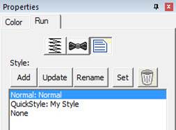
The Styles Property Window
Once you change the property of an object you just made, the
program takes the properties of that object and uses them for the next object
you make of the same type. This is the “Current Style.” For example, if you
create a run and set it to a Bean stitch, the next run you create will start out
as a Bean also. Although it may not be a named style, the current properties are
important, as they are used when creating an object.
Updating the ‘Current’ Style
The ‘Set’ button will use all of the properties as shown to
set the ‘Current’ style for new object creation; when you create a new object of
that same type (run, column, etc.) it will be created with the same settings as
the first object now selected.
Alternately, if you have an object whose style is “None” and
you click ‘Update’ it will likewise set the ‘Current’ digitizer settings to
match that object.
When you begin creating objects having just run the program,
the default styles are being used, called “Normal.” These have been tested to be
reasonable for all-around conditions, but naturally properties exist for a
myriad of reasons.
To remove the QuickStyle from an object, click “None.” This
will have no effect on the properties of the object; it just removes the style
setting.
When you have an object that has its properties set a certain
way, you can save those properties as a QuickStyle. Using QuickStyles allows you
to remember a set of property settings that sewed perfectly for a project, or
simply to match prior objects you’ve created.
Adding a QuickStyle
When you create a style based on a selected object, you can
name it. This is called a QuickStyle, and the style itself resides with the
design page being used, and on your computer for future use. To do this, click
the ‘Add’ button.
If you load a document with a style that is not on your
system, it will be referred to as a “Page Style”. If you would like to add this
style to your collection for use later, you can click the ‘Add’ button.
Renaming a QuickStyle
If you wish, you can rename the style with the ‘Rename’
button. Any object that uses this style will show the new name in use when the
style page is shown.
Updating a QuickStyle
When you have modified a QuickStyle-stylized object, and you
want to update the QuickStyle to match the current object properties, use the
‘Update’ button. This means that other objects with the same style set will not
match. Since the main reason for styles is to have all the objects working the
same, there is an option presented to update all the other objects that use the
same QuickStyle to have their properties match the current one.
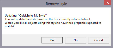
Removing a QuickStyle
Using the ‘Remove’ button, with the trash can icon on it, you
will remove the QuickStyle from the page, and from your system. Realize in doing
so that other objects on the page, or indeed other files you have created, may
have used that QuickStyle.
As QuickStyles are stored with the page as well, the style
will become a “Page Style” for other documents when you load them, if they had
that QuickStyle applied.
When you remove a QuickStyle, it erases it completely without
affecting the properties themselves. Objects that have had their QuickStyle
removed will not lose their property settings, but will naturally have a style
setting of “None.”
Stylesheets are design collections that have objects that have
properties set to perform digitizing a certain way.
For example, suppose you want to collect a set of object types
that you use to create freestanding lace. You can make a design with those
objects in it. Their shape does not matter, but their properties are what are
important. The objects will have the properties needed to make your lace. You
can then use that Stylesheet at any time to set all the object properties on the
sheet.
Stylesheets allow you to add styles to your Styles lists
quickly and easily. They can also be exported in a .BX installer for use on
multiple computers, or even shared with others.
Stylesheets can be loaded into the ‘current’ digitizer
settings, usually at the onset of creating a new design, but not always – they
can be set as the current properties at any time.
Creating a Stylesheet
Start with a new design page. Now begin by digitizing one
object, and set the properties of that object to your style. You can use a
QuickStyle that you have on hand already to set the properties. You can add as
many objects to the design as you like. Once you have the design how you want
it, use the menu ‘Create->Publish->Stylesheet’:
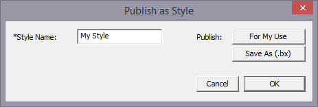 ’
’
You now have two options for Publishing: Publishing to your
collection of Stylesheets, or publishing as a .BX installer. The .BX option will
also publish to your stylesheet list, but it additionally saves a .BX file to a
location of your choosing.
Here is an example:
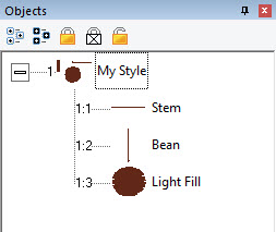
In this screenshot, you can see we have two Run objects,
labeled ‘Stem’ and ‘Bean’. We also have a Fill object, labeled, ‘Light
fill’.
IMPORTANT: Save your working (.be)
file so you can adjust this Stylesheet at a later date if you need
to.
When we publish this Stylesheet, we have these available as
QuickStyles:
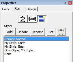
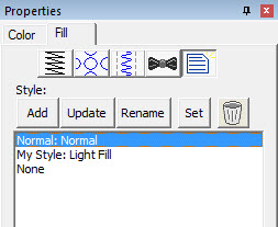
Notice there are now two entries on the Run (left) and one on
the Fill (right).
Setting a Style as Current
The menu ‘Create->Styles…’ calls up the Stylesheet
manager:
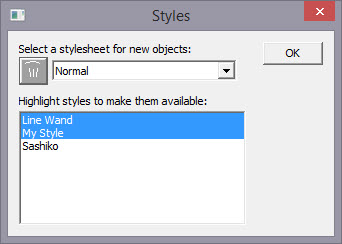
This window is divided into two sections. On the top is a list
of the Stylesheets available to be used to set the ‘current’ properties. The
lower list allows you to highlight any and all Stylesheets you want to have
available for use while creating a design.
Thus, you are not limited to a single Stylesheet, nor are you
restricted to using it only at the start of a design page. You can set the
properties to a style at any time by selecting it in the drop list. And you can
highlight as many stylesheets to be available as you like.
You will notice there are some Stylesheets that exist for you;
Normal (which is the default properties for the program) and ‘Line Wand’ which
is handy to use when generating objects with the ‘Magic Wand Lines’ tool. You’ll
notice that in the image above, there are two Stylesheets selected, “Line Wand’
and ‘My Style’, so here is what we see in the Run properties:
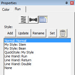
Notice that there are ‘My Style’ and ‘Line Wand’ available.
Also, we had chosen ‘Normal’ as the Stylesheet to use as a current property set,
so the Normal is there as well.
Note that QuickStyles are always available to you; they are
not a particular Stylesheet, but rather a simple set of properties for one
object type.
Removing a Stylesheet
When you select a Stylesheet that you have created, the
trashcan button next to the drop list will be active, allowing you to remove
that Stylesheet from your system completely. (Remember, we told you to save the
.BE file in case you want it later!)
Path Operations
Path operations are advanced graphical tools that help you
quickly get a result shape based on currently selected ones.
 Sometimes
you would like to be able to take a pair of scissors to a shape – make a wavy or
straight cut across it. You can do this with Breaklines. Using the ‘Break line’
button, having already selected a closed-outline Line object, you enter the
Break Mode. Next, select an input mode to draw your line across the shape, and
right-click to end drawing. You can edit the line before it is used. Once you
have the line as you would like, use the “Cut the object” button to make the
cut. You will now have multiple objects.
Sometimes
you would like to be able to take a pair of scissors to a shape – make a wavy or
straight cut across it. You can do this with Breaklines. Using the ‘Break line’
button, having already selected a closed-outline Line object, you enter the
Break Mode. Next, select an input mode to draw your line across the shape, and
right-click to end drawing. You can edit the line before it is used. Once you
have the line as you would like, use the “Cut the object” button to make the
cut. You will now have multiple objects.
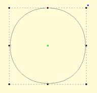
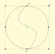
Start with a circle and draw a Breakline.
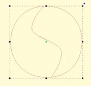
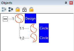
Cut the object with the Breakline. You can see it is now two
objects. 
A Fill stitch has been added and colors chosen.
 Cut is a
path operation that lets you remove a part of a shape, in the form of another
shape. Think in terms of a cookie cutter. There is a base shape (earliest in the
sequence), your dough in this example, and a cookie cutter on top. Position the
cutter as you like, select the two shapes, and click the Cut button. The base
object will now have its shape adjusted to have the area under the cutter
removed.
Cut is a
path operation that lets you remove a part of a shape, in the form of another
shape. Think in terms of a cookie cutter. There is a base shape (earliest in the
sequence), your dough in this example, and a cookie cutter on top. Position the
cutter as you like, select the two shapes, and click the Cut button. The base
object will now have its shape adjusted to have the area under the cutter
removed.
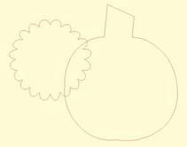
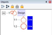
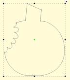
Here we use a couple shapes from the Library; the Pumpkin and
a Flower. Note the Pumpkin is the first object, which is the one that gets
operated on. Select both items and click the Cut button which gives the
appearance of a ‘bite’ being taken out of the pumpkin. Do we have rabbits in the
garden?
 This is a
more advanced operation where two or more shapes overlap one another, and you
want a new shape based on the area where the shapes overlap. The “AND” is where
this shape ‘and’ that shape both exist. It is used more for visual effects –
breaking a set of multiple overlapping shapes into even more parts. The results
of the AND operation are added after the last object used in the operation.
This is a
more advanced operation where two or more shapes overlap one another, and you
want a new shape based on the area where the shapes overlap. The “AND” is where
this shape ‘and’ that shape both exist. It is used more for visual effects –
breaking a set of multiple overlapping shapes into even more parts. The results
of the AND operation are added after the last object used in the operation.
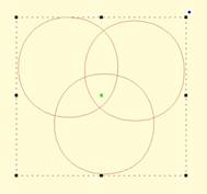
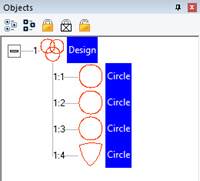
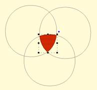
First, we merged three copies of a circle, then used the AND
button.
The result is shown as a red fill on the right.
Union
 When you
have two or more shapes that overlap, and you want to make a shape that
represents the entire outline of all the shapes, you use the Union button. This
could be effective for adding a border around a design. The new Union shape is
added to the design after the last of the shapes involved in the operation.
When you
have two or more shapes that overlap, and you want to make a shape that
represents the entire outline of all the shapes, you use the Union button. This
could be effective for adding a border around a design. The new Union shape is
added to the design after the last of the shapes involved in the operation.
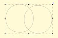
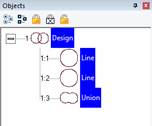
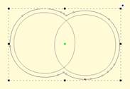
Two circles have been merged together on the left. Then the
Union button has been used to create the third object, a ‘Union’. The image on
the right shows the union object having been inflated so that it surrounds the
original two circles.
Flatten
 When
importing vector art from outside sources, it will be unlikely that the shapes
are truly ready for use in embroidery. Often times in the creation of vector art
it is expedient for the artist to layer one shape on top of another. In graphic
arts, only the final visible items will have any impact on the result, so any
shape or any part of a is shape may be hidden without consequence. In
embroidery, those shapes, as they exist, will be used. This means there will be
a tremendous amount of overlap. The Flatten command clips the shapes against
each other so that only one top layer remains. Remember that registration issues
will occur when you sew these objects, so you will likely need to do some
editing.
When
importing vector art from outside sources, it will be unlikely that the shapes
are truly ready for use in embroidery. Often times in the creation of vector art
it is expedient for the artist to layer one shape on top of another. In graphic
arts, only the final visible items will have any impact on the result, so any
shape or any part of a is shape may be hidden without consequence. In
embroidery, those shapes, as they exist, will be used. This means there will be
a tremendous amount of overlap. The Flatten command clips the shapes against
each other so that only one top layer remains. Remember that registration issues
will occur when you sew these objects, so you will likely need to do some
editing.

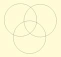
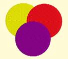
On the left is a graphic created and saved as an SVG. The
middle is the import of the SVG – notice the artist used three circles to create
the design, which seems reasonable enough. If we make them all fills (and set
colors, if needed) as we have on the right, it looks okay…
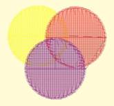
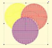
…But there is a problem. The design on the left is shown with
3D off so you can easily see the overlapping stitches. Once we use Flatten, as
in the design on the right, we are closer to having something that will sew
without damaging our needle or machine.
Inflating / Deflating shapes
 Sometimes
you need a shape to increase or decrease in size, but be exactly the same
distance around all the lines of the original. This means the new shape will
have to change. A classic example of this is echo quilting, where, as the lines
of stitching echo out, the curves become less tight, and fewer details are
visible.
Sometimes
you need a shape to increase or decrease in size, but be exactly the same
distance around all the lines of the original. This means the new shape will
have to change. A classic example of this is echo quilting, where, as the lines
of stitching echo out, the curves become less tight, and fewer details are
visible.
Clicking the Inflate button on the Tool Pane displays the
Inflate dialog, which allows you to inflate selected objects and their holes as
needed.
When inflating or deflating, the object selected will change.
Thus, if you wish to have the original shape retained on the page (for some
other part of the design) you should copy and paste it before inflating. See the
next section, ‘Automatic Outlining’ for an example use of inflation.
 Automatic
outlining will create a shape that surrounds any stitches on the design page.
This is useful when creating stitches that will add to an existing embroidery
design that has been merged onto the page.
Automatic
outlining will create a shape that surrounds any stitches on the design page.
This is useful when creating stitches that will add to an existing embroidery
design that has been merged onto the page.
Automatic outlining can also be used to create an object hole.
The purpose for this is for quilting designs. You can merge a design or create
an interior design with objects, then make a new outline in some larger shape,
for instance a quilt block, or your hoop. By adding a hole to that shape, in the
form of the current stitches on the page, you can create a stipple, or an echo
perhaps, that will surround those stitches and fill the block.
The automatic outlining can be combined with Inflation to
allow room around the stitches, for quilting or other purposes. For example,
there is a feature elsewhere in the platform that automatically creates
knockdown stitches for sewing on terry by first creating an automatic outline,
then inflating it slightly, and adding a light fill.
Here’s a quick illustration in use, starting with a basic
monogram:
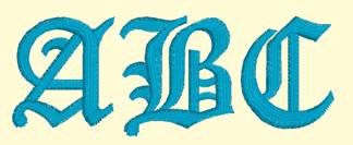
Now we will automatically outline it and set those new
objects to a backstitch, made green.

Let’s try a few more steps for
fun:
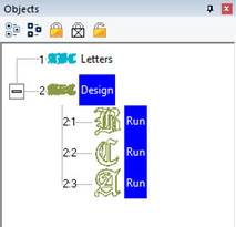
Copy the outlines that were created by
the Automatic Outline tool:
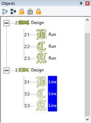
So, you should see this.
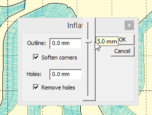
Use the Inflate button  to create echoed outlines of the
letters. Note the ‘Remove holes’ option is turned on. We are using a 5mm
inflation.
to create echoed outlines of the
letters. Note the ‘Remove holes’ option is turned on. We are using a 5mm
inflation.
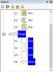
Add a Union. Next, delete the
individual ‘Line’ objects, as we won’t need them anymore.
Select the Union and use the menu
‘Create->outline->delete holes.’
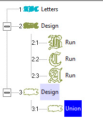
Now add a run to the Union, change
style, color, etc.
Publishing
When you want to create your own art and use them within other
designs, as motifs or embossing patterns, you can ‘Publish’ them in several
ways, including the creation of a .BX install-file which lets you share your
work with others.
Motifs are used in Motif Runs and Motif Fills. The motif
itself is a design, and can contain any number of Manual, Run and Satin objects,
although usually a motif is a singular Manual stitch object. Naturally, a motif
cannot contain another motif.
Motifs run left-to-right, by convention in the system. They do
get reversed when needed during a fill, but we start with a normal orientation.
A motif’s first point and its last point should line up – or rather, they will
when used so you might want to consider that as you draw one.
Motifs use the vertical position of the initial and final
points as a baseline, like a letter would. The baseline is how much above and
below the line the motif will sit.
Manual points are mostly used in motifs, especially since Runs
will calculate, and the points where a needle will land are unpredictable when
the user is in control of the size. This is doubly true when going around tight
curves, where small changes in size will very much affect the position of the
stitches.
You can use satins to make a motif, and the satin will
generate for the size used in the Motif run or Motif fill. It is generally not
needed to use any underlay in the satin, although you can.
Normal motifs are fairly small, typically 2-4mm, so as to be
used in a Motif Fill with a reasonable number visible, but they can be large, if
warranted. You may want to make a motif that represents a particular client
logo, and embed that in the background of a fill in a larger design.
When storing motifs, you will be saving them on your system
for use in the future, but when they are used within an object, they are also
stored in that object. This means that if you edit the motif, the object won’t
be updated – you’ll need to remove that motif from the object that’s using it,
and re-add the new version.
Let’s create a motif by drawing a shape and setting its type
to Manual. Note the first and last points are on the baseline.

Now we can publish it (along with any other designs on the
page). Click ‘For My Use’:

Now, let’s start a new Motif object. Click Add on the Motif
property and select the motif:

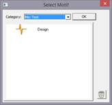
The motif, along with the result:

Creating Emboss Patterns
Embossing patterns can be either open or closed shapes, but
they will be used differently depending which they are. Open shapes are used as
repeating carving lines in a normal fill.
Closed shapes will have the fill stitches that lie internal to
the shape removed, unless that makes for an extra-long stitch. The effect of
closed shapes in a fill is that of satin areas within the fill, and those
provide dramatic relief from the fill stitching; almost a trapunto effect.
In order to ‘see’ more of the embossed pattern, keep its size
within the realm of your stitch length or smaller – typically 3.0mm - 5.5mm.
Embossing patterns are done with Line objects, as stitches
have no effect in the design. Also, you do not have to worry about transits,
overlap, and color or anything but the shape that is your desired result.
Emboss patterns are shapes that intersect the existing
stitches thus causing a needle-penetration. When the shape is parallel to the
stitches, it may not intersect; hence you can have sides of your shape that do
not create stitches. This is usually overcome by adjusting the inclination angle
a little bit, or rotating the emboss pattern, so that more intersections
occur.
Keep in mind what your emboss pattern will look where its
pattern will set next to a copy of itself; the design’s right edge shape will
interact with its left edge.
When storing emboss patterns, you will be saving them on your
system for use in the future, but when they are used within an object, they are
also stored in that object. This means that if you edit the pattern, the object
won’t be updated – you’ll need to remove that pattern from the object that’s
using it, and re-add the new version.
Let’s go through the process. Here we have drawn some line art
in two designs.


Next, we have a shape with a fill, and we’ll add an
embossing:


Notice the angle of inclination to cause more intersections in
the result:


Artwork drawn in the program can be exported as a vector file
in .svg format and for popular cutting machines. Use the menu ‘File->Export’
to save the artwork. This is not the same as the applique functions to save
cut-files (located on the Applique tab of the Color Window). Those outlines are
processed to directly cut an applique. The files saved when Exporting are the
objects as-drawn.
 Branching
is typically used to join the underlay of multiple satin columns, often for
lettering; however, it can also be used to travel through a set of objects,
beginning and ending where you select.
Branching
is typically used to join the underlay of multiple satin columns, often for
lettering; however, it can also be used to travel through a set of objects,
beginning and ending where you select.
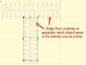
To branch a set of objects, select them and click the Branch
button, which is to the right of the Path tools. Branched objects will be
grouped if they are not already. To un-branch, select the first object and click
the Branch button off. Unbranching will ungroup if the objects were not
previously grouped.
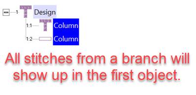
To set the entry and exit points for the branch, select at
least the first object in the branch. The entry and exit handles can lie on the
outline of the shape, or slightly outside it, which allows you to see them
better (even though the stitching will always begin on the outline.)

Here you can see the underlay for both objects has been sewn
before any topstitching:
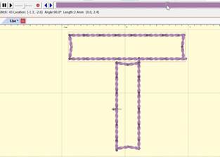
Branch objects will need to touch in order to join.
Objects that are left on their own or in groups separate from each other form a
subgroup, which will be branched together and then into the whole branch as
one.

Here you can see that the whole subgroup on the left will sew
first, as the branch ends in the subgroup on the right:
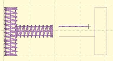
If we move the entry and exit to the same side:
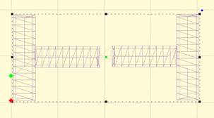
We can see that the branch will travel from the entry through
the first subpath, sew the second subpath, then come back and sew the first
subpath to its completion, ending at the exit point.
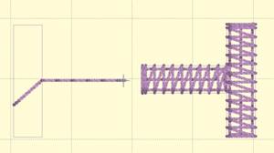
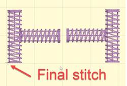
Objects that wholly contain other objects can produce
unpredictable results, so don’t do that with branching. However, if single runs
were used within a set of satins, then those will be discarded, as the branching
operation will provide its own transition runs. Also, branching will not
predictably discover objects within holes, so sequence those manually.
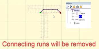
Objects of different types can be branched:
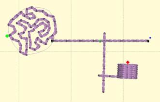
It is usually unwise to branch single runs, as the transition
runs that will go under them are likely to cause obvious weight to the run. But
if your single run is a bean, stemstitch, backstitch, etc. then your design
should sew just fine.
When a set of objects is branched, the sequence of those
objects will be determined by the branch, not the order in which they were
digitized. The exception to this is fully-digitized satin columns (not
auto-columns). When a branch encounters a set of fully-digitized columns, it
attempts to preserve the order of digitizing. The purpose of this is lettering.
In most embroidery, the order of overlapping adjacent objects is not terribly
important, but in lettering, this can be much more important as the eye is used
to seeing things a certain way. For example, in the following letter ‘A’ the
center horizontal bar should appear underneath both the left and right vertical
strokes regardless of the branch exit:
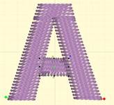
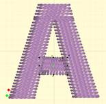
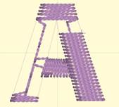
To accomplish this, the topstitching of the branch will be
done in a reverse fashion to end up at the exit, as seen in the above image,
which shows the letter partially stitched.
Object-based fonts can be published, which provide the user
with full stitch generation as they create, modify and resize lettering designs.
A font may be created on a design page (and saved normally as a .BE file) that
will hold a set of designs, each design with one or more objects. Fonts
may be multi-colored, and may use any stitch types, with the exception of
automatic satin columns or objects with breaklines. Those require processing
which makes their use in fonts slow or possibly with poor performance.
Fonts contain a set of individual glyphs such as the letters
A-Z or punctuation. Each glyph on the design page is represented as a design.
Thus, an English 26 letter alphabet will have 26 designs. If you add lowercase
letters, you’ll have 52 designs, etc. It does not matter where on the page the
designs are placed, nor does it matter in which order.
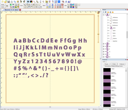
Each design is a glyph, named by the letter you type.
Each glyph, represented as a design, has a name. You can edit
the names in the Object Tree by clicking on the name, which will make the name
editable. The name is what the program will use to look up the design based on
what the user types. Generally, you will just type one key for a design name.
You may use upper and lower case in the naming; however, uppercase letters
should be followed by a letter ‘u’, ex: ‘Au’, ‘Bu’, ‘Cu’...
If you are creating a monogram font that has
position-dependent letters, you can create the left and right versions of the
letters similarly (you won’t have lowercase), ex: ‘Al’, ‘A’, ‘Ar’, ‘Bl’, ‘B’,
‘Br’… There are also such things as four-position monograms, making use of a
second name. To indicate the second name position, use ‘d’ ex: ‘Ad’.
Special characters such as punctuation are named normally. A
comma is ‘,’. Try to remember that users need to be able to type the letter you
are mapping in both Windows and Mac OS without Unicode.
Each glyph has a baseline object at the end of the design. The
lettering tool uses this to place the glyphs next to each other correctly. You
do not need to create the baselines manually because the first publish cycle
will add them for you if they’re not there already. You can then modify them up
or down, as needed, to place the glyph vertically. As an example, the lowercase
letter ‘y’ has a descender and you’ll need to move the baseline up accordingly.
You may even set your baseline through the center or at the top of your glyphs,
as required in monograms or other specialty fonts.
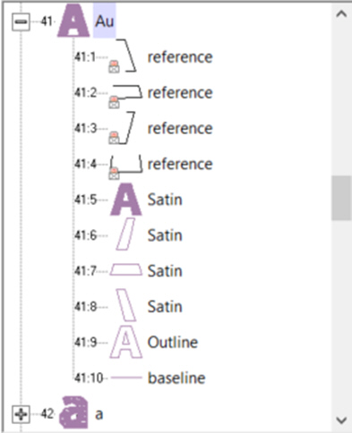
A typical letter design: Included are reference art,
branched satin columns, an optional outline, and a baseline. Baseline and
Outline are always Line object types. You do not need to draw the baseline. The
first publish cycle will add one for you, which you can later adjust.
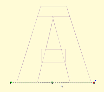
Baseline object selected
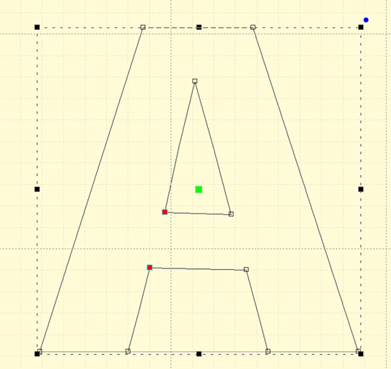
An optional outline selected
When the baselines are correct, and things look right, publish
again to make use of the lettering.
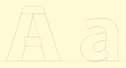
Letters on the baseline
If you have a row of letters, you might want to bring a rule
down from the ruler at the top of the page to ensure that the letter heights are
correct.
Note: The baseline must be the final object in each design,
and must not have any stitches applied.
Reference art may be included in the working file. We usually
label these as ‘reference’ and place them at the start, or start of each glyph,
depending how they were drawn and imported. Once the art is in place, lock it
using the Object Tree, which prevents inadvertent moves while digitizing.
We also create complete outlines as line objects. This is for
planned releases. You need not have this, but it will be useful going
forward.
When you publish a font, make sure that you have no lettering
designs on any design page which have that font (if previously published) in
use. If the font is in use, it cannot be updated by the publisher.
Publishing will place the font in your font folder as well as
make that font instantly available to the lettering system.
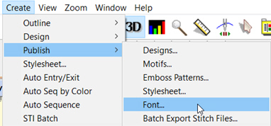
Size, Spacing and Kerning
When publishing a font, there are sizing issues to be aware
of.
Current Size
A font is digitized at a certain size – that is to say,
however you made it. Usually this is based on fitting the reference art onto the
design page. In typography, the uppercase ‘M’ is often considered the reference
letter for sizing, so if you don’t know what size to use, select the ‘M’ and
look at its height. Set that value in the Current height box.
Default Size
Fonts will load at a default size. This is usually what the
digitizer thinks of as the best size, or the size the work was created at to
stitch optimally. Set this value in the Default. Often, it is the same size as
the font has been digitized, therefore it would be the same as the Current
height.
Minimum and Maximum
Size
If you’ve played with embroidery fonts at all, you’ll know
there are limits to how well they’ll stitch at various sizes. Often the limits
of down to 50% or up to 250% are used, but you may wish to experiment and
discover the usable limits of the font. These limits only stop the user from
dragging the sizing handles with the mouse. They do not prevent someone from
overriding those limits by typing a value into the selection tool pane.
Spacing
Letter and word spacing are set as a percentage of height,
consistent with normal typography. A value of zero will cause letters or words
to have no separation. A value of 100% will cause things to separate to the
height on the font – almost always impossibly large. If you are unsure, try a
small value for letter spacing. Play around until you like it. Then use a low
multiple of that for word spacing, ex: 8% letter, 20% word.
Kerning
There is another process in typography called kerning. This
moves pairs of letters closer together, making the text more readable. Most
fonts will look better kerned. You might have something such as an athletic
applique where the font is designed to be spaced evenly, and this is known as
monospaced. That’s available by leaving the ‘Automatically kern’ checkbox
unchecked. If you are unsure, check it.
Nearest Point
Single color, satin-stitch-only, branched letters can be used
as Nearest-Connecting-Point (NCP, or simply Nearest Point) letters. NCP
lettering provides the ability to run right-to-left, center-out or any order the
user wants, with minimum travel or jump distances. This happens because the
letter’s stitches are sequenced so that the beginning and ending stitches are
near to the previous and next letters in the sequence. When digitizing a font
for NCP do not use runs to connect the satin elements, as these are created
during branching. If the publishing system sees runs, it will not create an NCP
letter, but will instead create a normal (and perfectly usable) letter,
as-digitized.
Note: the satin branching keeps the order of your digitizing
for layering purposes.
When publishing, you have choices for displaying the Nearest
Point setting to the user on their Stitch properties of a lettering design. The
choices are Always, Default On, Default Off and Never. The first three allow the
use of the nearest point setting.
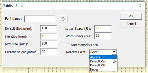
Always means you intend the font to always use the branching
NCP engine. Use this when you haven’t set the individual glyph entry/exits
because the font is known to operate well as branched. The use may not override
this setting.
Default On / Off settings allow the user to override your
preferred way of using the font. In most cases you will have digitized logical
entry and exit points on all your glyphs. If you have done so, the font will sew
as you intended it with the Nearest Point on or off, but Default On is
preferred. Alternately, you may know that some combinations of letters are not
as perfectly digitized as you would like, so you choose Default off, but leave
the option up to the user.
Never means you have not designed the font to branch
automatically.
Note: The Never setting does not mean you cannot branch within
a glyph when digitizing it. You still can, and those branches remain exactly as
you have set them. This setting is only to prevent the user from moving things
around.
Automatic Branch
During the publish phase, if the setting is Default on or
Always, the publishing system will check all the letters for you to see that
they are (and are able to be) branched. If some are not, the system will branch
those automatically, but only if they are all satin strokes.
Copyright
Publishing a font includes an optional step of adding
copyright information about the digitizer or company that has created the font.
The copyright fields allow you to claim your work as your own and set
permissions for its use. Each country has different copyright laws, though most
are generally the same. The U.S.A. has certain oddities of copyright law
regarding typefaces, so if you’re in business producing fonts, you might want to
look those up. You can also state the terms of usage, such as allowing people to
sell works created using your font.
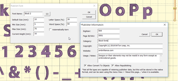
The copyright information is attached to each object in the
published font forever, even if the user is allowed to convert the lettering to
objects. Copyright information can be seen using the menu View>About this
page….
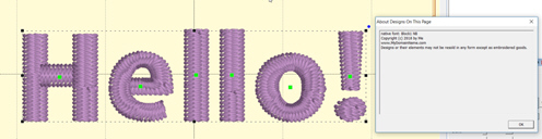
If you have copyright information entered for the font, you
will also be given a window to save the BX installer for that font. The BX files
allow you to share or even sell your fonts easily. User need only double click
the installer to load the font on Windows and/or MacOS.
Once you have entered publishing information, don’t forget to
save the .BE file in order to store that data there too. Publisher information
is stored in the file along with other data, and that is transferred to the
objects as they are placed on the page with a lettering tool.
The Digitizer field should contain you or your company’s name.
The optional Page ID is for those who track part numbers of their fonts, such as
in an e-commerce solution. The category field places your font in a subfolder
when installed, and may be useful in organizing fonts for the user. It is
usually left blank.
Convert to Objects
The checkbox, ‘Allow Convert to Objects’ does what its name
states thus enabling the users who have a high-enough level of the digitizer to
convert lettering designs into objects. This is your choice. It allows you to
control how others use the lettering designs, whether they are installed with BX
or even if you give them a .BE file. Some fonts are given out in .BE form as
training guides or as part of something more useful, while others are commercial
in nature and the digitizer prefers not to allow conversion of the lettering
into objects.
Conversion into objects allows the user to take a glyph and
manipulate it, which is commonly done for logo work. Many corporate logos begin
with a typical typeface and have glyph manipulation to make it specific to that
logo.
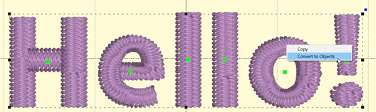
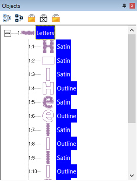
Objects that have been converted from a lettering design will
contain the same copyright information when using the menu View > About this
page.
Republishing
The option Allow Republishing is for those very generous souls
who allow others to add to, or modify, their work and pass it along. If another
user has your .BE file, or has imported all the glyphs by converting lettering
designs to objects, they may be allowed to make a new font out of it. Does this
replace the original copyright? No. Those objects are always tagged with each
copyright. The objects that the second user has modified will be able to have
another copyright added to the original. This can go on through as many people
as have republished the font. When more than one user’s work exists on the page,
all copyrights will appear.
If any user limits what can be done with the font, only that
user can adjust that setting. Subsequent publishers can add further restriction,
but not remove any. When a font is published, the publisher’s serial number is
turned into a unique identifier and placed in the copyright. This means a
publisher can modify their own settings, but they may not modify another
publisher’s settings.
We have made every effort to protect the work of individual
digitizers. We use encryption that’s state of the art. Of course, hackers are
always at work in the world, so there can be no guarantees. We all know that
locks are generally to keep honest folk out, and that’s what this is: a set of
locks. Of course, ordinary stitch files carry no information about their
digitizer, and they’re easily copied by any user, so this is a big improvement
over the status quo.
Foam Fonts
Foam fonts are published by setting the satin columns to the
style, “Foam” or using an automatic foam endcap or plank in the column underlay
properties. When publishing, the program notices the settings and flags the font
automatically.
When lettering with a foam font, Stitch properties are not
available, as the font should sew with the foam settings.
Good practice
When digitizing fonts, any normal quality procedures and
settings are going to work out. Remember that the user will have the ability to
override your settings for density, pattern and underlay, so there is no need to
make those adjustments across all letters. Keeping settings in synch is always a
headache anyway, although the use of Quick Styles does help enormously.
When making NCP fonts, remember to use only satin columns,
fully formed with inclination lines. Lay the satin columns in the order you
would normally, as if you were digitizing for a single sew-out. The main
difference is that you are leaving out connecting runs. For letters which are
normally digitized with extra pieces to accommodate overlap, such as is often in
‘X’ or ‘k’, don’t break those strokes down. The branching engine will do that
for the user.
Fonts typically have a wide size range and this causes issues
with overlapping elements. Serifs can get partially obscured in an enlarged
letter, so it might be best to consider sequencing those over the strokes that
connect to them. Underlaps are needed more on small letters than large ones. As
a letter is enlarged, you may see underlap build up a loft. Thus, we recommend
having overlap, but keep it minimal. You do not want to perfectly butt-join
objects, but rather prefer a minimal intersection, as necessary.
Remember that you can always edit a copy of your font at a
larger size to make it stitch well at those larger (or smaller) sizes.
The best recommendation we have for those new to font
digitizing is to look at our examples and then play with your own. Test, test,
test. And, please, never charge a consumer for something you have never tested
at all. Thank you!
Digitizing Tips for Font Creation
When making fonts, there are some basics that you need to
understand. First, and most important, is that fonts and embroidery are not
friends. Font designers get away with things that embroiderers cannot. Most
notably, font designers have no restrictions on stroke width – or the
variability of it. A glyph can have a super narrow column alongside a super fat
column. Assuming that you’re making a satin font, the lettering sizes are
restricted by these column widths. A minimum column width of 1.5mm is typical. A
maximum width of 7, 8 or even 9mm is about the most you will want to use, in
general circumstances. If your glyph has sections that are 7mm wide and sections
that are 2 mm wide, you have sizing constraints. The answer to this problem is
to make the font stroke thickness more regular. Embroidery font designers do
this all the time, and that’s often for fonts designed for a specific size. If
you’re making fonts that should be able to scale up or down, you need to pay
more attention to that problem.
The next issue is overlaps. Fonts on a computer don’t have
layers -- the letter is a filled color. With embroidery you can see the order
that the machine stitches the letter. And the human eye tends to have an opinion
about what looks right in that circumstance. There are also embroidery-related
reasons for having layers set correctly, particularly registration. Two satin
strokes that touch may have a slight gap, or a slight overlap, both of which may
not look right.
Another digitizing problem is turning acute angles. In a word,
our advice is, “Don’t.” Take a look at the following image which shows three
methods of turning tightly.
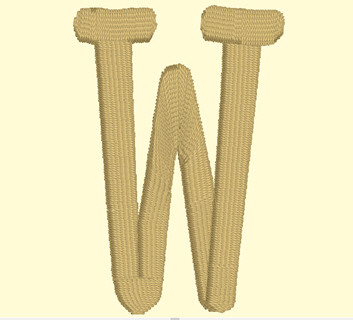
Three methods of turning
The bottom left, center, and bottom right are various methods
of turning tightly. Can you spot the worst one right away? If you said the
center, you are right. The center simply turns around, making long stitches and
high density (even with short-stitching). This turn is ugly and unnecessary.
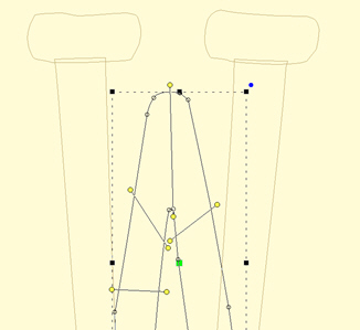
Look at the bottom right. This is a form of overlap, and there
are a couple ways to do it. This way doesn’t look bad in many cases and is easy
to accomplish. Its best benefit is that the stitch lengths remain at the width
of the columns.
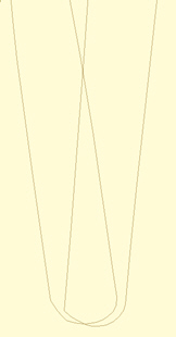
The bottom left has a couple things going on, including a cap
object, which is shaped like a bowl at the bottom of the letter. It also has the
two strokes coming down to the cap with nice, even, parallel stitches that
actually shorten just a bit as they get close to the cap. The strokes do not
overlap, but look like they do. They could overlap, but having them ‘kiss’ makes
for better branching, as this will look the same, no matter which way the letter
runs, left-to-right or right-to-left.
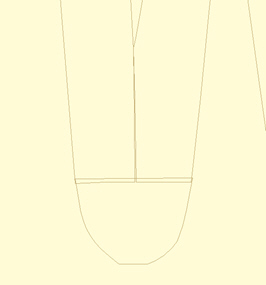
The downside of a cap is that it has to be a bit wide, and
that width may make for a long stroke, so keep it in mind. A way of dealing with
that problem is to adjust the shape of the letter.
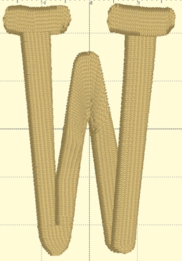
At first glance, you may not see the difference. Here, we made
the width of the cap narrower. In this case we set it to 7mm, which is
comfortable to sew and that allows this letter to sew at 35mm in height. Notice
that the left vertical stroke looks a bit wider at the top. We left it that way
so you could see how the verticals should narrow a bit in order to meet the cap
at its new width. You could accept the font like this, but it is more likely
that you’ll narrow the whole column.
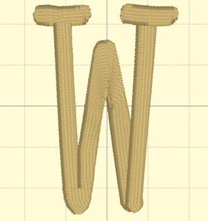
This version has been normalized a bit, so the columns are
slightly narrower. The result for the embroiderer is that this letter can sew
25% larger than when it was faithful to the original art.
Digitize your lettering for the approximate size you want it
sewn at. Naturally, having objects allows for the designs to be resized by the
user, and that’s nice, but if you would like a small version of the font, makes
one. Shrink it down in size and then study the column width. If you can, fatten
them up a bit, and you’ll have a smaller version of your font.
Connecting strokes
Consider the angle at which strokes connect. Right angles make
the strokes more obvious, tend to have shorter stitches, and provide branching a
way to move to the next stroke.
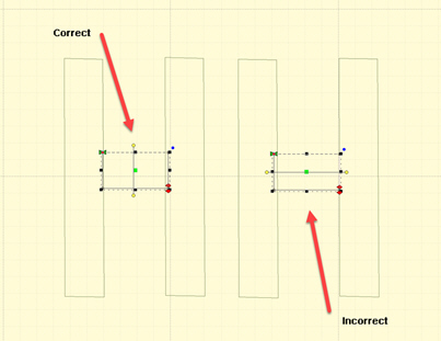
Keep strokes nearly perpendicular wherever possible
Strokes at angles have another set of possibilities. When the
angle is acute, you might be tempted to turn the inclination to be aligned with
the stroke it is meeting. This can be done for shallow entry angles.
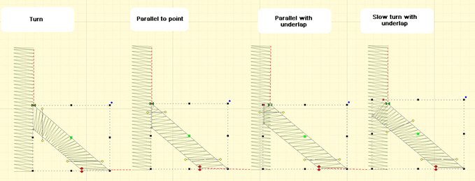
Stroke connection types
In the illustration we can see four common types of strokes.
The Turn is the most common and has issues with high density along the inside
edge. Short stitches can overcome this, as seen in the illustration, but it’s
going to be a more textured edge than the others and should be avoided unless
the turn is not significant.
The Parallel to Point is common, but has the disadvantage of
bringing a satin down to a point, which contributes to knotting underneath the
fabric and may even break needles.
Parallel with underlap has the advantage of smooth edges and
prevents the point issues by allowing the final stitches (show here at the top
of the right stroke) to have length reasonable enough to be sewn without
trouble.
The shallow turn with underlap also works because the density
variance is not so great as to attract attention and the final stitches are
long. The amount of overlap this uses can be a bit much if you’re making large
lettering. In that case, choose the Parallel with Underlap.
For small lettering you might consider a combination, shaped
similar to the parallel underlap but with the gradual turning inclination.
Whatever methods you employ, keep them consistent across the
font, where possible, especially in similar letters, such as M, N W, V. Bear in
mind the likely size of the letters when sewn, as size affects what you’ll do
when digitizing.
Size
The size you digitize to is somewhat important. If you
digitize at a large size, you’ll notice the design will change slightly when
reduced. Inclinations that look good at a larger size may not be appropriate
when the font is made small. We recommend you digitize the lettering at the
default size you want the font, then edit it at the smallest size you think it
should go. Going up in size does introduce some other issues but they are less
profound then going down in size.
When patterns are applied to satin objects, that pattern will
be kept throughout the usage of lettering. It will not be overridden by the
automatic pattern filling system in the lettering engine. This allows the
digitizer to specify the look of specific elements of the design. This is
normally not assigned for lettering, but is an option.
Naming of column objects can affect their adjustment in the
lettering generation process. Manual underlay columns, sometimes used to connect
perpendicular junctions, should not have additional underlay applied to them
during the lettering generation process. To prevent this, rename the column in
the object tree. Name them something such as ‘Underlay’ and they will not have
their underlay settings adjusted.
Create Font Page
The menu item Create > Publish > Create Font Page…
displays the operating system’s font selection window. Once you choose a font,
the program will create a new design page, on which will be a design for each
glyph in the typical font. This is a convenience item for those times you are
using TrueType as art.
Remember that most TT fonts have too many nodes and wildly
different stroke widths, so they are not usually good candidates for embroidery
unless you modify them heavily.
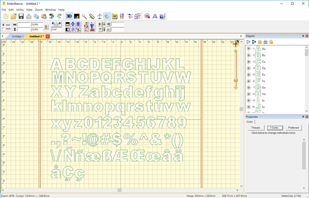
Each glyph comes in as a design, already named, along with
bitmap, baseline, and outlines for the glyph. We suggest you use the bitmap and
digitize over it. Breaking the outline into individual strokes usually will take
longer, and you’ll still have to compensate the objects by overlapping them
slightly.
You can delete the designs you don’t need and/or add more than
what comes in from the tool.
Due to the wildly different methods used by font designers to
publish their font, this tool is not able to be supported for specific fonts. It
can only work with the data given. If you see something strange or undesirable,
delete it.
Sharing designs with other users is easy: Simply offer a .BE
file and any Platform product or even the free Express Mode in the program will
allow someone to save it in the format they need for their machine.
You have two choices when you share.
1.)
Offer the file with all the digitizing objects.
This allows users
owning StitchArtist to modify your work for their own purposes. Sizing
capability is enhanced because the stitches will generate from the objects while
sizing.
2.) Save the file as a stitch file,
then re-import that.
This prevents users from
accessing your original objects.
Platform titles work as with any
stitch file, for example Essentials will be able to recalculate stitches, and/or
remove overlaps when combined, etc.
Note: If you have more than one
design, you may want to use the StitchArtist Level 3 menu command, Create >
Publish > Batch Export Stitch Files.
When creating designs for sale, you may want to export them as
stitch files for your customers. StitchArtist level 3 will export native
StitchArtist object-based designs to sets of stitch files for you.
Put the designs on a page, and name each design in the object
tree as you would like to see it saved. Ex: Tree will export to Tree.pes,
Tree.jef, etc.
You can only use this function on StitchArtist designs. It
cannot be used on imported stitch files. That’s not its purpose. The purpose is
to help you offer designs to customers who desire to simply use the file in
their machine without use of software.
The command is on the Create menu of StitchArtist 3 >
Publish > Batch Export Stitch Files. This will let you select a folder in
which to save the designs. All the current machine-readable formats will be
saved. What you do with the files after that is up to you – sort into folders by
file type, or design name, etc.